
User's Guide Part 1


User Guide: PTP 600 Series PTP 49600 reference information
phn-0896_009v003
Feb 2010
UNDER DEVELOPMENT
4-51
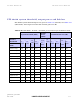
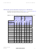
PTP 49600 system threshold, output power and link loss
PTP 49600 system threshold figures are given in Table 4-37 (IP mode) and Table 4-38
(TDM mode). These figures assume that antenna gain is 22 dBi.
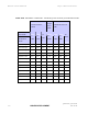
Table 4-37 PTP 49600 - IP mode - threshold, power and loss per modulation mode
Threshold Value
(dBm)
Output
Power
(dBm)
Maximum Link Loss
(dB)
Channel
Bandwidth
Modulation
Mode
5
MHz
10
MHz
20
MH
z
All
Bands
5
MHz
10
MHz
20
MHz
BPSK 0.63 single -98.6 -95.5 -91.9 +24 166.6 163.5 159.9
QPSK 0.63 single -94.3 -90.7 -87.5 +24 162.3 158.7 155.5
QPSK 0.87 single -90.8 -87.3 -84.0 +24 158.8 155.3 152.0
16QAM 0.63 single -88.7 -85.2 -81.8 +24 156.7 153.2 149.8
16QAM 0.63 dual -85.3 -81.6 -78.5 +24 153.3 149.6 146.5
16QAM 0.87 single -84.4 -80.6 -77.3 +24 152.4 148.6 145.3
16QAM 0.87 dual -81.0 -77.2 -74.5 +24 149.0 145.2 142.5
64QAM 0.75 single -81.2 -77.7 -74.7 +23 148.2 144.7 141.7
64QAM 0.75 dual -78.2 -74.7 -71.9 +23 145.2 141.7 138.9
64QAM 0.92 single -77.0 -73.9 -71.0 +21 142.0 138.9 136.0
64QAM 0.92 dual -74.0 -70.9 -67.6 +21 139.0 135.9 132.6
256QAM 0.81 single -75.2 -71.9 -68.0 +20 139.2 135.9 132.0
256QAM 0.81 dual -72.1 -68.4 -64.5 +20 136.1 132.4 128.5