
User's Guide Part 1


Site installation diagrams Chapter 2 Planning considerations
phn-0896_009v003
2-26
UNDER DEVELOPMENT
Feb 2010
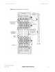
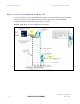
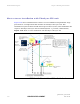
Site installation diagrams
This section contains diagrams to show how the components of PTP 600 sites are
installed and connected with LPU. The diagrams cover the following configurations:
• Typical mast or tower installation
• Typical wall installation
• Mast or tower installation with E1/T1
• Wall installation with E1/T1
• Mast or tower installation with GPS Sync Unit
• Wall installation with GPS Sync Unit
• Mast or tower installation with GPS Sync Unit and E1/T1
• Wall installation with GPS Sync Unit and E1/T1
The recommended standard components for protecting installations are:
• The supported Superior Essex cable
• Surge arrestor, type PTP-LPU: 4 or 8 per link (2 or 4 Motorola Kits Part Number
WB2907AA)
• Grounding stake
• Grounding cable: minimum size 8 AWG, preferably 6 or 4 AWG
• RJ45 screened connectors
Additional components are listed under each diagram where required. The
recommended cables are specified in Cables and connectors on
page 1-15.
There may be a local regulatory requirement to cross bond the CAT 5e cable to the
mast or tower at intervals as regular as every 10 metres (33 feet). This can be
achieved using an Andrew grounding assembly type 223158 or similar.
NOTE
Refer to instructions contained in the Andrew grounding kit for correct
installation, or if instructions are missing, refer to:
http://awapps.commscope.com/catalog/
product_details.aspx?id=15832&tab
=2
Where an installation already has, or requires the use of a Master Ground Bar then the
requirements of
Motorola Specification R56: STANDARDS AND GUIDELINES FOR
COMMUNICATION SITES (68P81089E50)
take precedence over those in this guide.