
User Manual
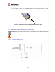
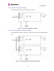
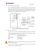
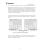

Table Of Contents
- 1 About This User Guide
- 2 Avoiding Hazards
- Getting Started
- 3.1 For Your Safety
- 3.2 Welcome
- 3.3 Product Description
- 3.4 Warranty
- 4 Product Architecture
- 5 General Considerations
- 5.1 Spectrum Planning
- 5.2 Licenses and Region Codes
- 5.3 Operational Restrictions
- 5.4 Channel Bandwidth Operation
- 5.5 PTP 54500 Specific Frequency Planning Considerations
- 5.6 PTP 58500 Specific Frequency Planning Considerations
- 5.7 Distance
- 5.8 Networking Information
- 5.9 Lightning Protection and Regulations
- 5.10 Electrical Requirements
- 6 Site Planning
- 6.1 Site Selection Criteria
- 6.1.1 ODU Site Selection
- 6.1.2 PTP 500 Series Bridge PIDU Plus Site Selection
- 6.1.3 Path Loss Considerations
- 6.1.4 Definitions
- 6.1.5 PTP 54500 Product Variant - Link Loss, Output Power and System Threshold versus Modulation Mode
- 6.1.6 PTP 58500 Product Variant - Link Loss, Output Power and System Threshold versus Modulation Mode
- 6.1 Site Selection Criteria
- 7 Installation
- 7.1 Preparation
- 7.2 Installation Procedure
- 7.3 Tools Required
- 7.4 Installation Support
- 7.5 Legal Disclaimer
- 7.6 Mounting the ODUs
- 7.7 Connecting Up
- 7.7.1 Preparing the PIDU Plus To ODU Cable
- 7.7.2 Making the Connections at the ODU
- 7.7.3 Making the PTP 300/500/600 Series Bridge PIDU Plus Connection At The ODU
- 7.7.4 Routing the Cable
- 7.7.5 Fitting a Lightning Protection Unit
- 7.7.6 Grounding the Installation
- 7.7.7 Making the ODU Connection at the PTP 300/500/600 Series Bridge PIDU Plus
- 7.7.8 Making the Network Connection at The PIDU Plus – PTP 500 Series Bridge
- 7.7.9 Mounting the PTP 300/500/600 Series Bridge PIDU Plus
- 7.7.10 Powering Up
- 7.7.11 Aligning the PTP 500 Series Bridge ODUs
- 7.7.12 Additional Installation Notes
- 8 Web Page Reference
- 8.1 Home Page – PTP 500 Series Bridge
- 8.2 Systems Status Page
- 8.3 System Administration Pages
- 8.3.1 System Configuration
- 8.3.2 Statistics Page
- 8.3.3 Detailed Counters Page
- 8.3.4 Install Pages
- 8.3.5 Graphical Install
- 8.3.6 Software Upgrade
- 8.3.7 Spectrum Management
- 8.3.7.1 Wireless Channels
- 8.3.7.2 Spectrum Management Measurements
- 8.3.7.3 Measurement Analysis
- 8.3.7.4 The Spectrum Management Master / Slave Relationship
- 8.3.7.5 Spectrum Management Configuration
- 8.3.7.6 Barring Channels
- 8.3.7.7 Master and Slave Channel Spectrum Graphics
- 8.3.7.8 Active Channel History
- 8.3.7.9 Viewing Historic Spectrum Management Metrics
- 8.3.8 Spectrum Management (Fixed Frequency)
- 8.3.9 Spectrum Management Control - With Operational Restrictions
- 8.3.10 Remote Management Page
- 8.3.10.1 Control Access to HTTP Interface
- 8.3.10.2 Control Access to Telnet Interface
- 8.3.10.3 SNMP (Simple Network Management Protocol)
- 8.3.10.4 Supported Management Information Bases (MIBS)
- 8.3.10.5 Diagnostics Alarms
- 8.3.10.6 SNMP Configuration
- 8.3.10.7 SMTP (Simple Mail Transport Protocol)
- 8.3.10.8 SNTP (Simple Network Time Protocol)
- 8.3.10.9 Setting the clock
- 8.3.11 Diagnostics
- 8.3.12 Change System Administration Password
- 8.3.13 License Key
- 8.3.14 Properties
- 8.3.15 Reboot
- 9 Recovery Mode
- 10 Fault Finding
- 11 Lightning Protection
- 12 Wind Loading
- 13 PTP 500 Series Bridge – Connectorized Model
- 13.1 Scope
- 13.2 Product Description
- 13.3 Software/Features
- 13.4 Deployment Considerations
- 13.5 Link Budget
- 13.6 Regulatory Issues
- 13.7 Installation
- 13.7.1 Antenna Choice
- 13.7.2 Cables and Connectors
- 13.7.3 Tools
- 13.7.4 Miscellaneous supplies
- 13.7.5 Mounting the Connectorized 500 Series Bridge
- 13.7.6 Mounting the antennas
- 13.7.7 Alignment Process
- 13.7.8 Aligning Dual Polar Antennas
- 13.7.9 Aligning Separate Antennas
- 13.7.10 Completing the Installation
- 13.7.11 Antenna Cable Fixing
- 13.7.12 Antenna Connection Weatherproofing
- 13.8 Additional Lightning Protection
- 14 Data Rate Calculations
- 15 AES Encryption Upgrade
- 16 Legal and Regulatory Notices
- 16.1 Important Note on Modifications
- 16.2 National and Regional Regulatory Notices – PTP 58500 variant
- 16.3 National and Regional Regulatory Notices – PTP 54500 Variant
- 16.4 Exposure
- 16.5 Legal Notices
- 16.5.1 Motorola Inc. End User License Agreement
- 16.5.1.1 Definitions
- 16.5.1.2 Grant of License
- 16.5.1.3 Conditions of Use
- 16.5.1.4 Title; Restrictions
- 16.5.1.5 Confidentiality
- 16.5.1.6 Right to Use Motorola’s Name
- 16.5.1.7 Transfer
- 16.5.1.8 Updates
- 16.5.1.9 Maintenance
- 16.5.1.10 Disclaimer
- 16.5.1.11 Limitation of Liability
- 16.5.1.12 U.S. Government
- 16.5.1.13 Term of License
- 16.5.1.14 Governing Law
- 16.5.1.15 Assignment
- 16.5.1.16 Survival of Provisions
- 16.5.1.17 Entire Agreement
- 16.5.1.18 Third Party Software
- 16.5.2 Hardware Warranty in U.S.
- 16.5.3 Limit of Liability
- 16.5.1 Motorola Inc. End User License Agreement
- 17 Specifications
- 18 FAQs
- 19 Glossary
- 20 Index

3 Getting Started
33
3.3.4 Remote LEDs and Recovery Switch
The PTP 300/500/600 Series Bridge PIDU Plus provides a facility to connect remote LEDs
and Recovery switch allowing the PIDU Plus to be mounted inside an enclosure. At the left
hand end of the PIDU Plus under the ODU connection cover can be found a PCB header and
three jumpers. Jumpers J906 and J907 should be removed and connection to the remote
LEDs and Recovery switch made to J908 as shown in Figure 9.
Figure 9 - Remote LED and Recovery Switch Wiring
3.3.5 Cables and connectors
The cable used to connect the PTP 300/500/600 Series Bridge PIDU Plus to the ODU can be
any standard CAT5e type provided that it is suitable for outdoor deployment. Motorola
recommends that cables to the specification below be used:
Cable: Superior Essex BBDGE CAT 5e
Connector Type: Tyco, 5-569278
Gland: Motorola WB1811
CAUTION: Failure to use the recommended (or equivalent) standard of cable may invalidate
the system’s safety certification.
The cable used to connect the PTP 500 Series Bridge PIDU Plus to the users Network
Equipment can be any standard CAT5e Cable.