
User Manual


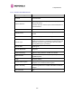
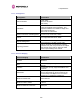

Table Of Contents
- 1 About This User Guide
- 2 Avoiding Hazards
- Getting Started
- 3.1 For Your Safety
- 3.2 Welcome
- 3.3 Product Description
- 3.4 Warranty
- 4 Product Architecture
- 5 General Considerations
- 5.1 Spectrum Planning
- 5.2 Licenses and Region Codes
- 5.3 Operational Restrictions
- 5.4 Channel Bandwidth Operation
- 5.5 PTP 54500 Specific Frequency Planning Considerations
- 5.6 PTP 58500 Specific Frequency Planning Considerations
- 5.7 Distance
- 5.8 Networking Information
- 5.9 Lightning Protection and Regulations
- 5.10 Electrical Requirements
- 6 Site Planning
- 6.1 Site Selection Criteria
- 6.1.1 ODU Site Selection
- 6.1.2 PTP 500 Series Bridge PIDU Plus Site Selection
- 6.1.3 Path Loss Considerations
- 6.1.4 Definitions
- 6.1.5 PTP 54500 Product Variant - Link Loss, Output Power and System Threshold versus Modulation Mode
- 6.1.6 PTP 58500 Product Variant - Link Loss, Output Power and System Threshold versus Modulation Mode
- 6.1 Site Selection Criteria
- 7 Installation
- 7.1 Preparation
- 7.2 Installation Procedure
- 7.3 Tools Required
- 7.4 Installation Support
- 7.5 Legal Disclaimer
- 7.6 Mounting the ODUs
- 7.7 Connecting Up
- 7.7.1 Preparing the PIDU Plus To ODU Cable
- 7.7.2 Making the Connections at the ODU
- 7.7.3 Making the PTP 300/500/600 Series Bridge PIDU Plus Connection At The ODU
- 7.7.4 Routing the Cable
- 7.7.5 Fitting a Lightning Protection Unit
- 7.7.6 Grounding the Installation
- 7.7.7 Making the ODU Connection at the PTP 300/500/600 Series Bridge PIDU Plus
- 7.7.8 Making the Network Connection at The PIDU Plus – PTP 500 Series Bridge
- 7.7.9 Mounting the PTP 300/500/600 Series Bridge PIDU Plus
- 7.7.10 Powering Up
- 7.7.11 Aligning the PTP 500 Series Bridge ODUs
- 7.7.12 Additional Installation Notes
- 8 Web Page Reference
- 8.1 Home Page – PTP 500 Series Bridge
- 8.2 Systems Status Page
- 8.3 System Administration Pages
- 8.3.1 System Configuration
- 8.3.2 Statistics Page
- 8.3.3 Detailed Counters Page
- 8.3.4 Install Pages
- 8.3.5 Graphical Install
- 8.3.6 Software Upgrade
- 8.3.7 Spectrum Management
- 8.3.7.1 Wireless Channels
- 8.3.7.2 Spectrum Management Measurements
- 8.3.7.3 Measurement Analysis
- 8.3.7.4 The Spectrum Management Master / Slave Relationship
- 8.3.7.5 Spectrum Management Configuration
- 8.3.7.6 Barring Channels
- 8.3.7.7 Master and Slave Channel Spectrum Graphics
- 8.3.7.8 Active Channel History
- 8.3.7.9 Viewing Historic Spectrum Management Metrics
- 8.3.8 Spectrum Management (Fixed Frequency)
- 8.3.9 Spectrum Management Control - With Operational Restrictions
- 8.3.10 Remote Management Page
- 8.3.10.1 Control Access to HTTP Interface
- 8.3.10.2 Control Access to Telnet Interface
- 8.3.10.3 SNMP (Simple Network Management Protocol)
- 8.3.10.4 Supported Management Information Bases (MIBS)
- 8.3.10.5 Diagnostics Alarms
- 8.3.10.6 SNMP Configuration
- 8.3.10.7 SMTP (Simple Mail Transport Protocol)
- 8.3.10.8 SNTP (Simple Network Time Protocol)
- 8.3.10.9 Setting the clock
- 8.3.11 Diagnostics
- 8.3.12 Change System Administration Password
- 8.3.13 License Key
- 8.3.14 Properties
- 8.3.15 Reboot
- 9 Recovery Mode
- 10 Fault Finding
- 11 Lightning Protection
- 12 Wind Loading
- 13 PTP 500 Series Bridge – Connectorized Model
- 13.1 Scope
- 13.2 Product Description
- 13.3 Software/Features
- 13.4 Deployment Considerations
- 13.5 Link Budget
- 13.6 Regulatory Issues
- 13.7 Installation
- 13.7.1 Antenna Choice
- 13.7.2 Cables and Connectors
- 13.7.3 Tools
- 13.7.4 Miscellaneous supplies
- 13.7.5 Mounting the Connectorized 500 Series Bridge
- 13.7.6 Mounting the antennas
- 13.7.7 Alignment Process
- 13.7.8 Aligning Dual Polar Antennas
- 13.7.9 Aligning Separate Antennas
- 13.7.10 Completing the Installation
- 13.7.11 Antenna Cable Fixing
- 13.7.12 Antenna Connection Weatherproofing
- 13.8 Additional Lightning Protection
- 14 Data Rate Calculations
- 15 AES Encryption Upgrade
- 16 Legal and Regulatory Notices
- 16.1 Important Note on Modifications
- 16.2 National and Regional Regulatory Notices – PTP 58500 variant
- 16.3 National and Regional Regulatory Notices – PTP 54500 Variant
- 16.4 Exposure
- 16.5 Legal Notices
- 16.5.1 Motorola Inc. End User License Agreement
- 16.5.1.1 Definitions
- 16.5.1.2 Grant of License
- 16.5.1.3 Conditions of Use
- 16.5.1.4 Title; Restrictions
- 16.5.1.5 Confidentiality
- 16.5.1.6 Right to Use Motorola’s Name
- 16.5.1.7 Transfer
- 16.5.1.8 Updates
- 16.5.1.9 Maintenance
- 16.5.1.10 Disclaimer
- 16.5.1.11 Limitation of Liability
- 16.5.1.12 U.S. Government
- 16.5.1.13 Term of License
- 16.5.1.14 Governing Law
- 16.5.1.15 Assignment
- 16.5.1.16 Survival of Provisions
- 16.5.1.17 Entire Agreement
- 16.5.1.18 Third Party Software
- 16.5.2 Hardware Warranty in U.S.
- 16.5.3 Limit of Liability
- 16.5.1 Motorola Inc. End User License Agreement
- 17 Specifications
- 18 FAQs
- 19 Glossary
- 20 Index

17 Specifications
216
17.1.3 Management
Management Specification
Status Indication
Power status
Ethernet Link Status
Data activity
Installation
Web server and browser for setup.
Audio tone feedback during installation , plus
graphical installation tool suitable for laptop and
PDA computing devices.
Web server for confirmation.
Radio Performance and Management Via web server and browser, SNMP
Alarms Via configurable email alerts, SNMP
System Management
Web or SNMP v1/v2c using MIBII, WiMAX MIB,
and a proprietary PTP MIB; Canopy Prizm.
Lightning protection
Built into the ODU; an external PTP Lightning
Protection Unit (PTP-LPU) end device is required
near the base of the tower or wall at the cable
entrance point leading to the network.
17.1.4 Ethernet Bridging
Ethernet Bridging Specification
Protocol IEEE802.3
QoS
IEEE 802.1p (eight levels), IEEE 802.1Q, IEEE
802.1ad.
Interface
10/100BaseT (RJ-45), Supports MDI/MDIX Auto
Crossover
Data Rates
Dynamically variable up to 105 Mbps at the
Ethernet (aggregate) for the Full version of the
product and up to 52 Mbps for the Lite version.
See Section 14 “Data Rate Calculations”.
Maximum Packet Rate 50000 frames/s
Maximum Frame Lifetime 1160 ms
Maximum Ethernet Frame Size 2000 bytes