
User Manual
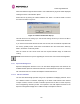


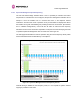
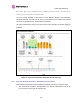
Table Of Contents
- 1 About This User Guide
- 2 Avoiding Hazards
- Getting Started
- 3.1 For Your Safety
- 3.2 Welcome
- 3.3 Product Description
- 3.4 Warranty
- 4 Product Architecture
- 5 General Considerations
- 5.1 Spectrum Planning
- 5.2 Licenses and Region Codes
- 5.3 Operational Restrictions
- 5.4 Channel Bandwidth Operation
- 5.5 PTP 54500 Specific Frequency Planning Considerations
- 5.6 PTP 58500 Specific Frequency Planning Considerations
- 5.7 Distance
- 5.8 Networking Information
- 5.9 Lightning Protection and Regulations
- 5.10 Electrical Requirements
- 6 Site Planning
- 6.1 Site Selection Criteria
- 6.1.1 ODU Site Selection
- 6.1.2 PTP 500 Series Bridge PIDU Plus Site Selection
- 6.1.3 Path Loss Considerations
- 6.1.4 Definitions
- 6.1.5 PTP 54500 Product Variant - Link Loss, Output Power and System Threshold versus Modulation Mode
- 6.1.6 PTP 58500 Product Variant - Link Loss, Output Power and System Threshold versus Modulation Mode
- 6.1 Site Selection Criteria
- 7 Installation
- 7.1 Preparation
- 7.2 Installation Procedure
- 7.3 Tools Required
- 7.4 Installation Support
- 7.5 Legal Disclaimer
- 7.6 Mounting the ODUs
- 7.7 Connecting Up
- 7.7.1 Preparing the PIDU Plus To ODU Cable
- 7.7.2 Making the Connections at the ODU
- 7.7.3 Making the PTP 300/500/600 Series Bridge PIDU Plus Connection At The ODU
- 7.7.4 Routing the Cable
- 7.7.5 Fitting a Lightning Protection Unit
- 7.7.6 Grounding the Installation
- 7.7.7 Making the ODU Connection at the PTP 300/500/600 Series Bridge PIDU Plus
- 7.7.8 Making the Network Connection at The PIDU Plus – PTP 500 Series Bridge
- 7.7.9 Mounting the PTP 300/500/600 Series Bridge PIDU Plus
- 7.7.10 Powering Up
- 7.7.11 Aligning the PTP 500 Series Bridge ODUs
- 7.7.12 Additional Installation Notes
- 8 Web Page Reference
- 8.1 Home Page – PTP 500 Series Bridge
- 8.2 Systems Status Page
- 8.3 System Administration Pages
- 8.3.1 System Configuration
- 8.3.2 Statistics Page
- 8.3.3 Detailed Counters Page
- 8.3.4 Install Pages
- 8.3.5 Graphical Install
- 8.3.6 Software Upgrade
- 8.3.7 Spectrum Management
- 8.3.7.1 Wireless Channels
- 8.3.7.2 Spectrum Management Measurements
- 8.3.7.3 Measurement Analysis
- 8.3.7.4 The Spectrum Management Master / Slave Relationship
- 8.3.7.5 Spectrum Management Configuration
- 8.3.7.6 Barring Channels
- 8.3.7.7 Master and Slave Channel Spectrum Graphics
- 8.3.7.8 Active Channel History
- 8.3.7.9 Viewing Historic Spectrum Management Metrics
- 8.3.8 Spectrum Management (Fixed Frequency)
- 8.3.9 Spectrum Management Control - With Operational Restrictions
- 8.3.10 Remote Management Page
- 8.3.10.1 Control Access to HTTP Interface
- 8.3.10.2 Control Access to Telnet Interface
- 8.3.10.3 SNMP (Simple Network Management Protocol)
- 8.3.10.4 Supported Management Information Bases (MIBS)
- 8.3.10.5 Diagnostics Alarms
- 8.3.10.6 SNMP Configuration
- 8.3.10.7 SMTP (Simple Mail Transport Protocol)
- 8.3.10.8 SNTP (Simple Network Time Protocol)
- 8.3.10.9 Setting the clock
- 8.3.11 Diagnostics
- 8.3.12 Change System Administration Password
- 8.3.13 License Key
- 8.3.14 Properties
- 8.3.15 Reboot
- 9 Recovery Mode
- 10 Fault Finding
- 11 Lightning Protection
- 12 Wind Loading
- 13 PTP 500 Series Bridge – Connectorized Model
- 13.1 Scope
- 13.2 Product Description
- 13.3 Software/Features
- 13.4 Deployment Considerations
- 13.5 Link Budget
- 13.6 Regulatory Issues
- 13.7 Installation
- 13.7.1 Antenna Choice
- 13.7.2 Cables and Connectors
- 13.7.3 Tools
- 13.7.4 Miscellaneous supplies
- 13.7.5 Mounting the Connectorized 500 Series Bridge
- 13.7.6 Mounting the antennas
- 13.7.7 Alignment Process
- 13.7.8 Aligning Dual Polar Antennas
- 13.7.9 Aligning Separate Antennas
- 13.7.10 Completing the Installation
- 13.7.11 Antenna Cable Fixing
- 13.7.12 Antenna Connection Weatherproofing
- 13.8 Additional Lightning Protection
- 14 Data Rate Calculations
- 15 AES Encryption Upgrade
- 16 Legal and Regulatory Notices
- 16.1 Important Note on Modifications
- 16.2 National and Regional Regulatory Notices – PTP 58500 variant
- 16.3 National and Regional Regulatory Notices – PTP 54500 Variant
- 16.4 Exposure
- 16.5 Legal Notices
- 16.5.1 Motorola Inc. End User License Agreement
- 16.5.1.1 Definitions
- 16.5.1.2 Grant of License
- 16.5.1.3 Conditions of Use
- 16.5.1.4 Title; Restrictions
- 16.5.1.5 Confidentiality
- 16.5.1.6 Right to Use Motorola’s Name
- 16.5.1.7 Transfer
- 16.5.1.8 Updates
- 16.5.1.9 Maintenance
- 16.5.1.10 Disclaimer
- 16.5.1.11 Limitation of Liability
- 16.5.1.12 U.S. Government
- 16.5.1.13 Term of License
- 16.5.1.14 Governing Law
- 16.5.1.15 Assignment
- 16.5.1.16 Survival of Provisions
- 16.5.1.17 Entire Agreement
- 16.5.1.18 Third Party Software
- 16.5.2 Hardware Warranty in U.S.
- 16.5.3 Limit of Liability
- 16.5.1 Motorola Inc. End User License Agreement
- 17 Specifications
- 18 FAQs
- 19 Glossary
- 20 Index

8 Web Page Reference
127
8.3.8 Spectrum Management (Fixed Frequency)
The PTP 500 Series Bridge software allows a user to optionally fix transmit and receive
frequencies for a wireless link. Once configured, the spectrum management software will not
attempt to move the wireless link to a channel with lower co and adjacent channel
interference. Therefore this mode of operation is only recommended for deployments where
the installer has a good understanding the prevailing interference environment. (See Section
8.3.4.3 “Wireless Configuration”). Care must also be taken to ensure that the frequency
allocations at each end of the link are compatible. To help the user when identifying the mode
of operation Spectrum Management uses two visual cues. See Figure 62.
The main page title identifies the mode of operation using the “Fixed Frequency Mode” postfix
and the selected channels are identified by a red capital ‘F’.
Figure 62 - Spectrum Management Fixed Frequency Screen
Channel barring is disabled in fixed frequency mode; it is not required as dynamic channel
hopping is prohibited in this mode.