
User Manual

Getting Started
30
Caution: Failure to use the recommended (or equivalent) standard of cable may invalidate the
system’s safety certification.
The cable used to connect the PTP 500 Series Bridge PIDU Plus to the users Network Equipment
can be any standard CAT5e Cable.
The PIDU Plus to ODU and the PIDU Plus to Network Equipment cables may be unscreened
(UTP) or screened (STP). However, unscreened cables reduce the system’s ability to cope with
nearby lightning strikes. If lightning activity is common in the area of deployment, the use of
screened cable is highly recommended. See Section 11 “Lightning Protection”.
The PIDU Plus provides screen continuity between the ODU and Network Equipment connections.
Note:The ODU network connection implements automatic MDI/MDI-X sensing and pair swapping
allowing connection to networking equipment that require cross-over cables (MDI-X networks) or
straight-through cables (MDI Networks).
3.3.6 PTP and Lightning Protection
The PTP 500 Series Bridge PIDU Plus meets the low level static discharge specifications identified
in Section 17 “Specifications”, but does not provide lightning or surge suppression. Installations
will generally require lightning or surge suppression, a separate Ethernet surge suppressor must
be used and appropriately earthed. Suitable surge suppressors can be sourced from your Motorola
Point-to-Point Distributor or Solutions Provider. See Section 11 “Lightning Protection”.
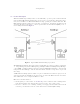
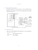
3.3.7 Mounting Brackets
The PTP 500 Series Bridge is supplied with a mounting bracket suitable for mounting the ODU
to a pole of 50mm (2”) to 75mm (3”) in diameter. For more details on mounting, see Section 7
“Installation”.
The bracket allows for adjustment in both azimuth and elevation. The bracket may be split
allowing the pole mount section of the bracket to be mounted to the pole first. This allows the
installer to take the weight of the unit and secure it, one handed, with a single mounting bolt.
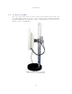
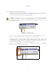
The PIDU Plus can either be desk or wall mounted. The preference is wall mounted with the
cables dressed to a cable channel. Wall mounting is achieved by screwing through the mounting
lugs on either side of the unit. Remember to leave space for access to the Recovery button. See
Section 3.3.2 “PIDU Plus – PTP 500 Series Bridge”.
3.3.8 Configuration and Management
Configuration and Management of the PTP 500 Series Bridge is implemented using an inbuilt web
server hosting a number of Configuration and Management web pages. This approach allows Con-
figuration and Management to be carried out on any standard web browsing technology. The PTP
500 Series Bridge can also be managed remotely using the SNMP management protocol. Connec-
tion to the bridge is via the Ethernet connection carrying the bridge network traffic. Connection
to the unit is via a preset IP address. This address can be changed via the Network Interface
Configuration web page. A full explanation of the available web pages and their use can be found
in Section 8 “Web Page Reference”.