
User Manual
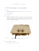

PTP 500 Series Bridge - Connectorized Model
146
In non-FCC regions antenna choice is not restricted but any region specific EIRP limit must be
obeyed by reducing the maximum Transmit power
23
, see Table 6 in Section 5.2 “Region Codes”.
In FCC regions external antennas from the list in Section 13.6.3 “Antennas for USA / Canada –
5.8 GHz” can be used with the Connectorized version of the 500 Series Bridge. These are approved
by the FCC for use with the product and are basically constrained by the following limits:
• Single Polarization Flat Plate Antennas – up to 28 dBi per antenna.
• Single/Dual Polarization Parabolic Dish Antennas – up to 37.7 dBi per polarization or antenna.
In FCC regions when using external antennas – cable loss between the connectorized version of
the 500 Series Bridge and the antenna ports must not be less than 1.2 dB.
13.2.3 Antenna Choices – 5.4 GHz
The integrated antenna has a gain of 23.5 dBi.
In FCC regions external antennas from the list in Section 13.2.3 “Antenna Choices – 5.4 GHz”
can be used with the Connectorized version of the 500 Series Bridge. These are approved by the
FCC for use with the product and are basically constrained by the following limits:
• Single/Dual Polarization Parabolic Dish Antennas – up to 34.6 dBi per polarization or antenna.
However, the Maximum Transmit Power must be reduced to avoid exceeding the EIRP limits. In
FCC regions when using external antennas – cable loss between the connectorized version of the
500 Series Bridge and the antenna ports must not be less than 1.2 dB.
13.3 Software/Features
The connectorized variant operates in the same way as the basic 500 Series and is released initially
with the feature set to the Connectorized 500 Series variant. The areas where the functionality is
modified are:
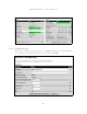
13.3.1 Status Page
The link loss calculation presented on the Status Page of the management interface has to be
modified to allow for the increased antenna gains at each end of the link. The manufacturing
process of the Connectorized 500 Series Bridge configures the standard hardware of the unit for
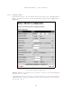
use with external antennas. The installer is prompted, as part of the installation process, to enter
the gain of the external antenna(s) and cable losses at each end of the link.
Peer-to-peer messaging is used to pass the effective antenna gain to each end of the link so that
the link loss calculations can be correctly computed.
Maximum Transmit Power Allowed = EIRP Limit – Antenna Gain + Cable Losses; set the power to the 1dB value
23
lower than the actual value calculated.