
User Manual

Lightning Protection
140
11.3.1 Pre-Power Testing
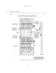
Before plugging the RJ45 from the lower LPU (or if not fitted the ODU) into the PIDU, check the
following resistances at the RJ45:
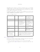
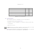
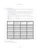
1. Check the cable resistance between pins 1&2, 3&6, 4&5 and 7&8 at the RJ45. Check against
column 2 in Table 17. Resistances for each pair should be within 1 ohm of each other.
2. Check the cable resistance between pins 1&3 and 4&7 at the RJ45. Check against columns 3
and 4 respectively in Table 17.
3. Ensure that there is greater than 100K ohms between pins 1&8 for all cable lengths.
4. Ensure that there is greater than 100K ohms between pin 1 and ODU ground for all cable
lengths.
5. Ensure that there is greater than 100K ohms between pin 8 and ODU ground for all cable
lengths.
CAT-5 Length
(Meters)
Resistance
between pins 1&2,
3&6 , 4&5 and
pins 7&8 (ohms)
Resistance
between pins 1&3
(ohms)
Resistance
between pins 4&7
(ohms)
0 0.8 1.0 1.6
10 2.5 2.7 3.3
20 4.2 4.4 5.0
30 5.9 6.1 6.7
40 7.6 7.8 8.4
50 9.3 9.5 10.1
60 11.0 11.2 11.8
70 12.7 12.9 13.5
80 14.4 14.6 15.2
90 16.1 16.3 16.9
100 17.8 18.0 18.6
Table 17 Resistance Table Referenced to the RJ45 at the PIDU Plus
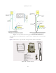
11.3.2 Post-Power Testing
The Correct Operation is as follows: