
Installation Guide
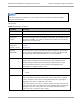
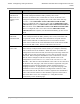
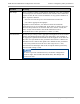
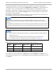


Table Of Contents
- PMP 450i and PTP 450i Configuration and User Guide
- Safety and regulatory information
- Contents
- List of Figures
- List of Tables
- About This Configuration and User Guide
- Chapter 1: Reference information
- Chapter 2: Configuration
- Preparing for configuration
- Task 1: Connecting to the unit
- Task 2: Configuring IP and Ethernet interfaces
- Configuring the AP IP interface
- NAT, DHCP Server, DHCP Client and DMZ in SM
- Configuring the SM IP interface with NAT disabled
- Configuring the SM IP interface with NAT enabled
- NAT tab of the SM with NAT disabled
- NAT tab of the SM with NAT enabled
- Reconnecting to the management PC
- VLAN Remarking and Priority bits configuration
- VLAN tab of the AP
- VLAN tab of the SM
- VLAN Membership tab of the SM
- PPPoE tab of the SM
- NAT Port Mapping tab of the SM
- Task 3: Upgrading the software version and using CNUT
- Task 4: Configuring General and Unit settings
- Task 5: Configuring security
- Isolating APs from the internet
- Encrypting radio transmissions
- Managing module access by passwords
- Requiring SM Authentication
- Filtering protocols and ports
- Encrypting downlink broadcasts
- Isolating SMs
- Filtering management through Ethernet
- Allowing management only from specified IP addresses
- Configuring management IP by DHCP
- Restricting radio Telnet access over the RF interface
- Security tab of the AP
- Filtering protocols and ports
- Protocol Filtering tab of the AP
- Port configuration tab of the AP
- Security tab of the SM
- Protocol Filtering tab of the SM
- Port Configuration tab of the SM
- Task 6: Configuring radio parameters
- Task 7: Setting up SNMP agent
- Task 8: Configuring syslog
- Task 9: Configuring remote access
- Task 10: Monitoring the AP-SM Link
- Task 11: Configuring quality of service
- Maximum Information Rate (MIR) Parameters
- Token Bucket Algorithm
- MIR Data Entry Checking
- Committed Information Rate (CIR)
- Bandwidth from the SM Perspective
- Interaction of Burst Allocation and Sustained Data Rate Settings
- High-priority Bandwidth
- Traffic Scheduling
- Setting the Configuration Source
- Quality of Service (QoS) tab of the AP
- DiffServ tab of the AP
- Quality of Service (QoS) tab of the SM
- DiffServ tab of the SM
- Task 12: Performing an Sector Wide SA
- Task 13: Zero Touch Configuration Using DHCP Option 66
- Task 14: Configuring Radio via config file
- Task 15: Configuring a RADIUS server
- Understanding RADIUS for PMP 450i
- Choosing Authentication Mode and Configuring for Authentication Servers - AP
- SM Authentication Mode – Require RADIUS or Follow AP
- Handling Certificates
- Configuring your RADIUS servers for SM authentication
- Assigning SM management IP addressing via RADIUS
- Configuring your RADIUS server for SM configuration
- Using RADIUS for centralized AP and SM user name and password management
- RADIUS Device Data Accounting
- RADIUS Device Re-authentication

PMP 450i and PTP 450i Configuration and User
Task 6: Configuring radio parameters
Attribute Meaning
Broadcast
Repeat Count
The default is 2 repeats (in addition to the original broadcast packet,
for a total of 3 packets sent for every one needed), and is settable to
1 or 0 repeats (2 or 1 packets for every broadcast).
ARQ (Automatic Repeat reQuest) is not present in downlink
broadcast packets, since it can cause unnecessary uplink traffic from
every SM for each broadcast packet. For successful transport without
ARQ, the AP repeats downlink broadcast packets. The SMs filter out
all repeated broadcast packets and, thus, do not transport further.
The default of 2 repeats is optimum for typical uses of the network as
an internet access system. In applications with heavy download
broadcast such as video distribution, overall throughput is
significantly improved by setting the repeat count to 1 or 0. This
avoids flooding the downlink with repeat broadcast packets.
Transmitter
Output Power
This value represents the combined power of the AP’s two
transmitters.
Nations and regions may regulate transmitter output power. For
example
• 5 GHz modules are available as connectorized radios, which
require the operator to adjust power to ensure regulatory
compliance.
The professional installer of the equipment has the responsibility to
• maintain awareness of applicable regulations.
• calculate the permissible transmitter output power for the
module.
• confirm that the initial power setting is compliant with national or
regional regulations.
• confirm that the power setting is compliant following any reset of
the module to factory defaults.
External Gain
This value needs to correspond to the published gain of the antenna
used to ensure the radio will meet regulatory requirements.
SM Receive
Target Level
Each SM’s Transmitter Output Power is automatically set by the AP.
The AP monitors the received power from each SM, and adjusts each
SM’s Transmitter Output Power so that the received power at the AP
from that SM is not greater what is set in this field. This value
represents the transmitted and received power (combined power)
perceived on the SM.
114
pmp-0957 (April 2015)