
User's Manual

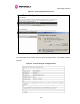
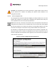
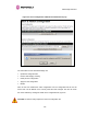


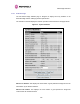

Table Of Contents
- PTP 600 User Guide
- Copyright Information
- Contents
- 1 About This User Guide
- 2 Avoiding Hazards
- Getting Started
- 4 Product Architecture
- 5 Radio Link Planning and Regulations
- 5.1 Spectrum Planning
- 5.2 Licenses and Region Codes
- 5.3 Operational Restrictions
- 5.4 Variable Channel Bandwidth Operation
- 5.5 PTP 25600 Specific Frequency Planning Considerations
- 5.6 PTP 45600 Specific Frequency Planning Considerations
- 5.7 PTP 48600 Specific Frequency Planning Considerations
- 5.8 PTP 49600 Specific Frequency Planning Considerations
- 5.9 PTP 54600 Specific Frequency Planning Considerations
- 5.10 PTP 58600 Specific Frequency Planning Considerations
- 5.11 PTP 59600 Specific Frequency Planning Considerations
- 5.12 Time Division Duplex (TDD) Synchronization
- 5.13 Link Mode Optimization
- 5.14 Distance
- 5.15 Networking Information
- 5.16 Lightning Protection
- 5.17 Electrical Requirements
- 5.18 Latency
- 6 Site Planning
- 6.1 Site Survey and Link Planning
- 6.2 Site Selection Criteria
- 6.2.1 ODU Site Selection
- 6.2.2 PTP 600 Series Bridge PIDU Plus Site Selection
- 6.2.3 Path Loss Considerations
- 6.2.4 Definitions
- 6.2.5 PTP 25600 System Threshold, Output Power and Link Loss
- 6.2.6 PTP 45600 System Threshold, Output Power and Link Loss
- 6.2.7 PTP 48600 System Threshold, Output Power and Link Loss
- 6.2.8 PTP 49600 System Threshold, Output Power and Link Loss
- 6.2.9 PTP 54600 System Threshold, Output Power and Link Loss
- 6.2.10 PTP 58600 System Threshold, Output Power and Link Loss
- 6.2.11 PTP 59600 System Threshold, Output Power and Link Loss
- 7 Installation
- 7.1 Preparation
- 7.2 Installation Procedure
- 7.3 Tools Required
- 7.4 Installation Support
- 7.5 Legal Disclaimer
- 7.6 Mounting the ODUs
- 7.7 Connecting Up
- 7.7.1 Preparing the PIDU Plus To ODU Cable
- 7.7.2 Making the Connections at the ODU
- 7.7.3 Making the PTP 600 Series Bridge PIDU Plus Connection At The ODU
- 7.7.4 Routing the Cable
- 7.7.5 Fitting a Lightning Protection Unit
- 7.7.6 Grounding the Installation
- 7.7.7 Making the ODU Connection at the PTP 600 Series Bridge PIDU Plus
- 7.7.8 Making the Network Connection at The PIDU Plus – PTP 600 Series Bridge
- 7.7.9 Mounting the PTP 600 Series Bridge PIDU Plus
- 7.7.10 Powering Up
- 7.8 Establishing a Radio Link
- 8 Web Page Reference
- 8.1 Home Page – PTP 600 Series Bridge
- 8.2 Systems Status Page
- 8.3 System Administration Pages
- 8.3.1 System Configuration
- 8.3.2 Statistics Page
- 8.3.3 Detailed Counters Page
- 8.3.4 Install Pages
- 8.3.5 Graphical Install
- 8.3.6 Software Upgrade
- 8.3.7 Spectrum Management
- 8.3.8 Spectrum Management (Fixed Frequency)
- 8.3.9 Spectrum Management Control - With Operational Restrictions
- 8.3.10 Spectrum Management – Example of PTP 25600 Product variant
- 8.3.11 Remote Management Page
- 8.3.12 Diagnostics
- 8.3.13 Change System Administration Password
- 8.3.14 License Key
- 8.3.15 Properties
- 8.3.16 Reboot
- 9 Recovery Mode
- 10 Lightning Protection
- 10.1 Overview
- 10.2 Detailed Installation
- 10.3 Installation Wiring
- 10.4 LPU Recommended Configurations
- 10.4.1 Typical Mast or Tower Installation
- 10.4.2 Typical Wall Installation
- 10.4.3 Mast or Tower Installation with E1/T1
- 10.4.4 Wall Installation with E1/T1
- 10.4.5 Mast or Tower Installation with GPS Sync Box
- 10.4.6 Wall Installation with GPS Sync Box
- 10.4.7 Mast or Tower Installation with GPS Sync Box and E1/T1
- 10.4.8 Wall Installation with GPS Sync Box and E1/T1
- 11 Troubleshooting (Fault Finding)
- 12 Wind Loading
- 13 Connectorized PTP 600 Series Bridge
- 13.1 Scope
- 13.2 Product Description
- 13.3 Software/Features
- 13.4 Deployment Considerations
- 13.5 Link Budget
- 13.6 Regulatory Issues with Connectorized Units
- 13.7 Installation
- 13.7.1 Antenna Choice
- 13.7.2 Cables and Connectors
- 13.7.3 Tools
- 13.7.4 Miscellaneous supplies
- 13.7.5 Mounting the Connectorized 600 Series Bridge
- 13.7.6 Mounting the antennas
- 13.7.7 Alignment Process
- 13.7.8 Aligning Dual Polar Antennas
- 13.7.9 Aligning Separate Antennas
- 13.7.10 Completing the Installation
- 13.7.11 Antenna Cable Fixing
- 13.7.12 Antenna Connection Weatherproofing
- 13.8 Additional Lightning Protection
- 14 TDD Synchronization Configuration and Installation Guide
- 15 E1/T1 Installation Guide
- 16 Data Rate Calculations
- 17 AES Encryption Upgrade
- 18 Remote Software Upgrade by TFTP
- 19 Legal and Regulatory Notices
- 19.1 Important Note on Modifications
- 19.2 National and Regional Regulatory Notices – PTP 49600 variant
- 19.3 National and Regional Regulatory Notices – PTP 59600 variant
- 19.4 National and Regional Regulatory Notices – PTP 58600 variant
- 19.5 National and Regional Regulatory Notices – PTP 54600 Variant
- 19.6 National and Regional Regulatory Notices – PTP 25600 Variant
- 19.7 Exposure
- 19.8 Legal Notices
- 20 Specifications
- 20.1 System Specifications
- 20.1.1 Wireless PTP 25600 Variant
- 20.1.2 Wireless PTP 45600 Variant
- 20.1.3 Wireless PTP 48600 Variant
- 20.1.4 Wireless PTP 49600 Variant
- 20.1.5 Wireless PTP 54600 Variant
- 20.1.6 Wireless PTP 58600 Variant
- 20.1.7 Wireless PTP 59600 Variant
- 20.1.8 Management
- 20.1.9 Ethernet Bridging
- 20.1.10 Physical
- 20.1.11 Powering
- 20.1.12 Telecoms Interface
- 20.2 Safety Compliance
- 20.3 EMC Emissions Compliance
- 20.4 EMC Immunity Compliance
- 20.5 Radio Certifications
- 20.6 Environmental Specifications
- 20.7 System Connections
- 20.1 System Specifications
- 21 FAQs
- 22 Glossary
- 23 Index

8 Web Page Reference
154
Figure 66 - Telecoms Data Entry
Telecoms Interface: May be either T1 or E1, reflecting the Installation Wizard setting.
Line Code: Displays the Line Code setting for each channel. The Line Code configuration
must match the configuration of the connected equipment and may be set using the
Installation Wizard.
Cable Length: The Cable Length setting is applicable in T1 mode only and shows the cable
length specified in the installation wizard.
Loopback: Allows the T1 or E1 data stream to be looped back at the copper or wireless
interface. During normal operation the loopback must be set to "None". It may be helpful
during installation to test the telecoms links by performing loopback connections.
A "Copper" loopback connects the received data on a given telecoms interface to the transmit
interface. A "Copper" loopback may be used, in conjunction with a Bit Error Rate Tester, to
confirm that the correct connections have been made to the ODU. This mode cannot be used
for resistance tests as it is only capable of looping back valid telecoms signals.
A "Wireless" loopback sends the telecoms data received across the wireless link back across
the link on the same Telecom channel. The link may be checked using, for example, a Bit
Error Rate Tester to ensure that no errors are detected.
A typical T1 or E1 installation might include a "Copper" loopback on the local unit followed by
a "Wireless" loopback on the remote unit.