
User's Manual
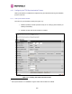
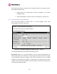


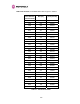
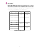
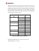

Table Of Contents
- 1 About This User Guide
- 2 Avoiding Hazards
- Getting Started
- For Your Safety
- 3.2 Welcome
- 3.3 Product Description
- 3.4 Warranty
- 4 Product Architecture
- 5 General Considerations
- 5.1 Spectrum Planning
- 5.2 Introducing the Time Division Duplex (TDD) Synchronization Feature
- 5.3 Region Codes
- 5.4 Operational Restrictions
- 5.5 2.5GHz Specific Frequency Planning Considerations
- 5.6 5.4GHz Specific Frequency Planning Considerations
- 5.7 5.8GHz Specific Frequency Planning Considerations
- 5.8 Distance
- 5.9 Networking Information
- 5.10 Lightning Protection
- 5.11 Electrical Requirements
- 6 Site Planning
- 6.1 Site Selection Criteria
- 6.1.1 ODU Site Selection
- 6.1.2 PTP 600 Series Bridge PIDU Plus Site Selection
- 6.1.3 Path Loss Considerations
- 6.1.4 Definitions
- 6.1.5 2.5 GHz Product Variant - Receive Sensitivity, Link Loss, Output Power and Threshold Vs Modulation Mode
- 6.1.6 5.4 GHz Product Variant - Receive Sensitivity, Link Loss, Output Power and Threshold Vs Modulation Mode
- 6.1.7 5.8 GHz Product Variant - Receive Sensitivity, Link Loss, Output Power and Threshold Vs Modulation Mode
- 6.1 Site Selection Criteria
- 7 Installation
- 7.1 Preparation
- 7.2 Installation Procedure
- 7.3 Tools Required
- 7.4 Installation Support
- 7.5 Legal Disclaimer
- 7.6 Mounting the ODUs
- 7.7 Connecting Up
- 7.7.1 Preparing The PIDU Plus To ODU Cable
- 7.7.2 Making the Connections at the ODU
- 7.7.3 Making the PTP 600 Series Bridge PIDU Plus Connection At The ODU
- 7.7.4 Routing the Cable
- 7.7.5 Fitting A Surge Arrestor
- 7.7.6 Grounding the Installation
- 7.7.7 Making the ODU Connection at the PTP 600 Series Bridge PIDU Plus
- 7.7.8 Making the Network Connection at The PIDU Plus – PTP 600 Series Bridge
- 7.7.9 Mounting the PTP 600 Series Bridge PIDU Plus
- 7.7.10 Powering Up
- 7.7.11 Aligning the PTP 600 Series Bridge ODUs
- 8 Web Page Reference
- 8.1 Home Page – PTP 600 Series Bridge
- 8.2 Systems Status Page
- 8.3 System Administration Pages
- 8.3.1 System Configuration
- 8.3.2 Statistics Page
- 8.3.3 Detailed Counters Page
- 8.3.4 Install Pages
- 8.3.5 Graphical Install
- 8.3.6 Software Upgrade
- 8.3.7 Spectrum Management
- 8.3.7.1 Wireless Channels
- 8.3.7.2 Spectrum Management Measurements
- 8.3.7.3 Measurement Analysis
- 8.3.7.4 The Spectrum Management Master / Slave Relationship
- 8.3.7.5 Spectrum Management Configuration
- 8.3.7.6 Barring Channels
- 8.3.7.7 Local and Peer Channel Spectrum Graphics
- 8.3.7.8 Active Channel History
- 8.3.7.9 Viewing Historic Spectrum Management Metrics
- 8.3.8 Spectrum Management (Fixed Frequency and WIMAX)
- 8.3.9 Spectrum Management Control - With Operational Restrictions
- 8.3.10 Spectrum Management – Example of 2.5 GHz Product variant
- 8.3.11 Remote Management Page
- 8.3.12 Diagnostics
- 8.3.13 Change System Administration Password
- 8.3.14 License Key
- 8.3.15 Properties
- 8.3.16 Reboot
- 9 Recovery Mode
- 10 Fault Finding
- 11 Lightning Protection
- 12 Wind Loading
- 13 PTP 600 Series Bridge – Connectorized Model
- 13.1 Scope
- 13.2 Product Description
- 13.3 Software/Features
- 13.4 Deployment Considerations
- 13.5 Link Budget
- 13.6 Regulatory Issues
- 13.7 Antennas for USA / Canada
- 13.8 Installation
- 13.8.1 Antenna Choice
- 13.8.2 Cables and Connectors
- 13.8.3 Tools
- 13.8.4 Miscellaneous supplies
- 13.8.5 Mounting the Connectorized 600 Series Bridge
- 13.8.6 Mounting the antennas
- 13.8.7 Alignment Process
- 13.8.8 Aligning Dual Polar Antennas
- 13.8.9 Aligning Separate Antennas
- 13.8.10 Completing the Installation
- 13.8.11 Antenna Cable Fixing
- 13.8.12 Antenna Connection Weatherproofing
- 13.9 Additional Lightning Protection
- 14 TDD Synchronization Configuration and Installation Guide
- 15 E1/T1 Installation Guide
- 16 Lightning Protection
- 17 Data Rate Calculations
- 18 AES Encryption Upgrade
- 19 Legal and Regulatory Notices
- 20 Glossary
- 21 FAQs
- 22 Index Alar

217
NOTE: In TDM link optimization mode, burst duration should be selected so as to achieve the
lowest latency consistent with throughput sufficient to support the maximum allowed
configuration of internal TDM interfaces at the most robust modulation mode.
1231HTable 29 lists
the frame duration thresholds for TDM operation. Frame duration depends on burst duration.
Burst duration should be selected by testing each of the values available in the applicable
bandwidth combination, starting with the shortest burst duration, until the resulting frame
duration falls within the limits listed in
1232HTable 29.
Bandwidth Combination
(MHz)
Frame Duration
(microseconds)
Burst Duration
(microseconds)
≤ 2079 µs 726 µs
> 2079 µs, ≤ 3145 µs 1088 µs
30
> 3145 µs 1451 µs
5/10/30 > 0 1088 µs
≤ 2079 µs 726 µs 15/30
> 2079 µs 1451 µs
≤ 2079 µs 726 µs
> 2079 µs 1451 µs
15
Not used 2176 µs
10/15 > 0 2176 µs
≤ 2747 µs 1088 µs 10
> 2747 µs 2176 µs
5 > 0 1088 µs
Table 29 - Burst Durations in TDM Link Optimization
Slave Receive to Transmit Gap: This is a calculated value (default is 29).
TDD Holdover Mode: Strict or Best Effort