
User's Manual
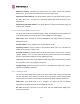

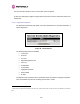
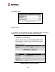
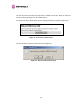

Table Of Contents
- 1 About This User Guide
- 2 Avoiding Hazards
- Getting Started
- For Your Safety
- 3.2 Welcome
- 3.3 Product Description
- 3.4 Warranty
- 4 Product Architecture
- 5 General Considerations
- 5.1 Spectrum Planning
- 5.2 Introducing the Time Division Duplex (TDD) Synchronization Feature
- 5.3 Region Codes
- 5.4 Operational Restrictions
- 5.5 2.5GHz Specific Frequency Planning Considerations
- 5.6 5.4GHz Specific Frequency Planning Considerations
- 5.7 5.8GHz Specific Frequency Planning Considerations
- 5.8 Distance
- 5.9 Networking Information
- 5.10 Lightning Protection
- 5.11 Electrical Requirements
- 6 Site Planning
- 6.1 Site Selection Criteria
- 6.1.1 ODU Site Selection
- 6.1.2 PTP 600 Series Bridge PIDU Plus Site Selection
- 6.1.3 Path Loss Considerations
- 6.1.4 Definitions
- 6.1.5 2.5 GHz Product Variant - Receive Sensitivity, Link Loss, Output Power and Threshold Vs Modulation Mode
- 6.1.6 5.4 GHz Product Variant - Receive Sensitivity, Link Loss, Output Power and Threshold Vs Modulation Mode
- 6.1.7 5.8 GHz Product Variant - Receive Sensitivity, Link Loss, Output Power and Threshold Vs Modulation Mode
- 6.1 Site Selection Criteria
- 7 Installation
- 7.1 Preparation
- 7.2 Installation Procedure
- 7.3 Tools Required
- 7.4 Installation Support
- 7.5 Legal Disclaimer
- 7.6 Mounting the ODUs
- 7.7 Connecting Up
- 7.7.1 Preparing The PIDU Plus To ODU Cable
- 7.7.2 Making the Connections at the ODU
- 7.7.3 Making the PTP 600 Series Bridge PIDU Plus Connection At The ODU
- 7.7.4 Routing the Cable
- 7.7.5 Fitting A Surge Arrestor
- 7.7.6 Grounding the Installation
- 7.7.7 Making the ODU Connection at the PTP 600 Series Bridge PIDU Plus
- 7.7.8 Making the Network Connection at The PIDU Plus – PTP 600 Series Bridge
- 7.7.9 Mounting the PTP 600 Series Bridge PIDU Plus
- 7.7.10 Powering Up
- 7.7.11 Aligning the PTP 600 Series Bridge ODUs
- 8 Web Page Reference
- 8.1 Home Page – PTP 600 Series Bridge
- 8.2 Systems Status Page
- 8.3 System Administration Pages
- 8.3.1 System Configuration
- 8.3.2 Statistics Page
- 8.3.3 Detailed Counters Page
- 8.3.4 Install Pages
- 8.3.5 Graphical Install
- 8.3.6 Software Upgrade
- 8.3.7 Spectrum Management
- 8.3.7.1 Wireless Channels
- 8.3.7.2 Spectrum Management Measurements
- 8.3.7.3 Measurement Analysis
- 8.3.7.4 The Spectrum Management Master / Slave Relationship
- 8.3.7.5 Spectrum Management Configuration
- 8.3.7.6 Barring Channels
- 8.3.7.7 Local and Peer Channel Spectrum Graphics
- 8.3.7.8 Active Channel History
- 8.3.7.9 Viewing Historic Spectrum Management Metrics
- 8.3.8 Spectrum Management (Fixed Frequency and WIMAX)
- 8.3.9 Spectrum Management Control - With Operational Restrictions
- 8.3.10 Spectrum Management – Example of 2.5 GHz Product variant
- 8.3.11 Remote Management Page
- 8.3.12 Diagnostics
- 8.3.13 Change System Administration Password
- 8.3.14 License Key
- 8.3.15 Properties
- 8.3.16 Reboot
- 9 Recovery Mode
- 10 Fault Finding
- 11 Lightning Protection
- 12 Wind Loading
- 13 PTP 600 Series Bridge – Connectorized Model
- 13.1 Scope
- 13.2 Product Description
- 13.3 Software/Features
- 13.4 Deployment Considerations
- 13.5 Link Budget
- 13.6 Regulatory Issues
- 13.7 Antennas for USA / Canada
- 13.8 Installation
- 13.8.1 Antenna Choice
- 13.8.2 Cables and Connectors
- 13.8.3 Tools
- 13.8.4 Miscellaneous supplies
- 13.8.5 Mounting the Connectorized 600 Series Bridge
- 13.8.6 Mounting the antennas
- 13.8.7 Alignment Process
- 13.8.8 Aligning Dual Polar Antennas
- 13.8.9 Aligning Separate Antennas
- 13.8.10 Completing the Installation
- 13.8.11 Antenna Cable Fixing
- 13.8.12 Antenna Connection Weatherproofing
- 13.9 Additional Lightning Protection
- 14 TDD Synchronization Configuration and Installation Guide
- 15 E1/T1 Installation Guide
- 16 Lightning Protection
- 17 Data Rate Calculations
- 18 AES Encryption Upgrade
- 19 Legal and Regulatory Notices
- 20 Glossary
- 21 FAQs
- 22 Index Alar

155
The trace selection allows the user to control which traces are plotted.
As with other management pages the page refresh period can be used to interactively monitor the
wireless link.
8.3.12.2 Diagnostics Download
The diagnostics Download page allows the system administrator to download snapshots of
system diagnostics.
Figure 88 - CSV Download
The following diagnostics are available:
• Vector Error
• Rx Power
• Tx Power
• Signal Strength Ratio V/H
• Link Loss
• Rx Data Rate
• Tx Data Rate
• Aggregate Data Rate
• Receive SNR
• Rx Gain
All diagnostics are extracted from the associated status and statistics web page histograms.
They are translated in a CSV file containing at most 5784
22F
23
entries.
23
5784 entries comprises 3600 entries for the first hour, 1440 entries for the next 24 hours and 744 entries for the next 31
days.