
User's Manual

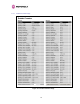

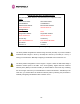
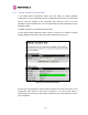
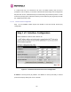


Table Of Contents
- 1 About This User Guide
- 2 Avoiding Hazards
- Getting Started
- For Your Safety
- 3.2 Welcome
- 3.3 Product Description
- 3.4 Warranty
- 4 Product Architecture
- 5 General Considerations
- 5.1 Spectrum Planning
- 5.2 Introducing the Time Division Duplex (TDD) Synchronization Feature
- 5.3 Region Codes
- 5.4 Operational Restrictions
- 5.5 2.5GHz Specific Frequency Planning Considerations
- 5.6 5.4GHz Specific Frequency Planning Considerations
- 5.7 5.8GHz Specific Frequency Planning Considerations
- 5.8 Distance
- 5.9 Networking Information
- 5.10 Lightning Protection
- 5.11 Electrical Requirements
- 6 Site Planning
- 6.1 Site Selection Criteria
- 6.1.1 ODU Site Selection
- 6.1.2 PTP 600 Series Bridge PIDU Plus Site Selection
- 6.1.3 Path Loss Considerations
- 6.1.4 Definitions
- 6.1.5 2.5 GHz Product Variant - Receive Sensitivity, Link Loss, Output Power and Threshold Vs Modulation Mode
- 6.1.6 5.4 GHz Product Variant - Receive Sensitivity, Link Loss, Output Power and Threshold Vs Modulation Mode
- 6.1.7 5.8 GHz Product Variant - Receive Sensitivity, Link Loss, Output Power and Threshold Vs Modulation Mode
- 6.1 Site Selection Criteria
- 7 Installation
- 7.1 Preparation
- 7.2 Installation Procedure
- 7.3 Tools Required
- 7.4 Installation Support
- 7.5 Legal Disclaimer
- 7.6 Mounting the ODUs
- 7.7 Connecting Up
- 7.7.1 Preparing The PIDU Plus To ODU Cable
- 7.7.2 Making the Connections at the ODU
- 7.7.3 Making the PTP 600 Series Bridge PIDU Plus Connection At The ODU
- 7.7.4 Routing the Cable
- 7.7.5 Fitting A Surge Arrestor
- 7.7.6 Grounding the Installation
- 7.7.7 Making the ODU Connection at the PTP 600 Series Bridge PIDU Plus
- 7.7.8 Making the Network Connection at The PIDU Plus – PTP 600 Series Bridge
- 7.7.9 Mounting the PTP 600 Series Bridge PIDU Plus
- 7.7.10 Powering Up
- 7.7.11 Aligning the PTP 600 Series Bridge ODUs
- 8 Web Page Reference
- 8.1 Home Page – PTP 600 Series Bridge
- 8.2 Systems Status Page
- 8.3 System Administration Pages
- 8.3.1 System Configuration
- 8.3.2 Statistics Page
- 8.3.3 Detailed Counters Page
- 8.3.4 Install Pages
- 8.3.5 Graphical Install
- 8.3.6 Software Upgrade
- 8.3.7 Spectrum Management
- 8.3.7.1 Wireless Channels
- 8.3.7.2 Spectrum Management Measurements
- 8.3.7.3 Measurement Analysis
- 8.3.7.4 The Spectrum Management Master / Slave Relationship
- 8.3.7.5 Spectrum Management Configuration
- 8.3.7.6 Barring Channels
- 8.3.7.7 Local and Peer Channel Spectrum Graphics
- 8.3.7.8 Active Channel History
- 8.3.7.9 Viewing Historic Spectrum Management Metrics
- 8.3.8 Spectrum Management (Fixed Frequency and WIMAX)
- 8.3.9 Spectrum Management Control - With Operational Restrictions
- 8.3.10 Spectrum Management – Example of 2.5 GHz Product variant
- 8.3.11 Remote Management Page
- 8.3.12 Diagnostics
- 8.3.13 Change System Administration Password
- 8.3.14 License Key
- 8.3.15 Properties
- 8.3.16 Reboot
- 9 Recovery Mode
- 10 Fault Finding
- 11 Lightning Protection
- 12 Wind Loading
- 13 PTP 600 Series Bridge – Connectorized Model
- 13.1 Scope
- 13.2 Product Description
- 13.3 Software/Features
- 13.4 Deployment Considerations
- 13.5 Link Budget
- 13.6 Regulatory Issues
- 13.7 Antennas for USA / Canada
- 13.8 Installation
- 13.8.1 Antenna Choice
- 13.8.2 Cables and Connectors
- 13.8.3 Tools
- 13.8.4 Miscellaneous supplies
- 13.8.5 Mounting the Connectorized 600 Series Bridge
- 13.8.6 Mounting the antennas
- 13.8.7 Alignment Process
- 13.8.8 Aligning Dual Polar Antennas
- 13.8.9 Aligning Separate Antennas
- 13.8.10 Completing the Installation
- 13.8.11 Antenna Cable Fixing
- 13.8.12 Antenna Connection Weatherproofing
- 13.9 Additional Lightning Protection
- 14 TDD Synchronization Configuration and Installation Guide
- 15 E1/T1 Installation Guide
- 16 Lightning Protection
- 17 Data Rate Calculations
- 18 AES Encryption Upgrade
- 19 Legal and Regulatory Notices
- 20 Glossary
- 21 FAQs
- 22 Index Alar

113
Tx Multicasts: Total number of good multicast packets.
Tx Collisions: Total number frames experiencing collisions.
Tx 64 Bytes: Total number 64 byte frames transmitted
Tx 65 to 127 Bytes: Total number frames transmitted in the size range 65 to 127 bytes.
Tx 128 to 255 Bytes: Total number frames transmitted in the size range 128 to 255 bytes.
Tx 256 to 511 Bytes: Total number frames transmitted in the size range 256 to 511 bytes.
Tx 512 to 1023 Bytes: Total number frames transmitted in the size range 512 to 1023 bytes.
Tx 1024 to Max: Total number frames transmitted in the size range 1024 to Maximum bytes.
Tx FIFO Drops: Total number frames dropped due to lack of capacity in the transmit buffer,
for example when the 600 Series bridge is connected to the local Ethernet at a connection
speed of less than 1 Gbps.
Rx & Tx High Priority: Total number of received or transmitted frames marked as high
priority.
Rx & Tx Low Priority: Total number of received or transmitted frames marked as low priority.
Rx & Tx Pause Frames: Total number of received or transmitted pause frames.
Rx Classifier Drops: Total number of received frames dropped due to the application of
classifier rules.
Statistics Page Refresh Period: The statistics page refreshes automatically according to the
setting entered here (in seconds).
8.3.4 Install Pages
These pages are used during system installation. There follows a description of the install
pages along with their use during the installation configuration process. The actual installation
process is described in Section
1093H7.7.11.
All wireless links are shipped as paired units. They are pre-configured at the factory so that
they can be installed without the user supplying any configuration. Each wireless link is
shipped with a quick start guide. Attached to the quick start guide is a summary of the pre-
configured configuration data.
1094HTable 14 shows a sample link configuration. The values
highlighted have been committed to the wireless unit’s non-volatile storage.