
User guide

S1A0071 Audio Processor for Class-D Power AMP
Digital & Analog Co., Ltd. (Rev. 1.0) -15-
9. APPLICATION NOTE
Note 1
The OPT [Active high] controls the power on mute function [referred to Note 7]. User can prevent the
unstable operation by using this pin and use can use this signal to prevent the POP noise during the
power-on time.
Note 2
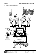
The OSCEN pin controls the direction of OSC pin because OSC has a bidirectional operation. The
S1A0071 has a built-in triangle oscillator, so user can selectable to use the internal oscillator or
external oscillator. If user wants to internal oscillator, the OSCEN pin connects to VCC then OSC is
output port and used to detect the internal oscillation waveform. If user want to make an amplifier with
three or more channels set, at this case, user muse be careful to make a system, specially the setting
of oscillator frequency, because when user can use the each independent internal oscillators
configuration, the system can be generated from mixed modulation resulting from the frequency
deviation between oscillators in each chip, respectively. In such case, the oscillator in one of the IC’s
must be MASTER, shared with the other IC’s oscillator signal, and the oscillator in the other IC’s must
disabled by the use of the OSCEN pin (SLAVE mode). Then, the OSCEN pin of MASTER ICs is
connected to VCC (or Open) and the OSCEN pin of the other IC (Slaves) must be grounded (GND),
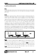
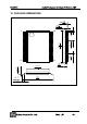
and the SIO pins must be connected to each other. As you can see the Figure 1, the oscillator signal
of the MASTER IC provides the triangle wave to the Slave ICs.
OSCEN
SIO
IC1
VCC
OSCEN
SIO
IC4
OSCEN
SIO
IC3
Figure 1. Multi Chip Application
Note 3
MUΤΕ Pin controls the switching operation of MOSFET [Active Low]. When Mute Pin is low, the
PO_R, NO_R, PO_R and NO_R signal go to low level so the MOSFET operation is stop. Sound is not
heard any more. This operation can be use as protection condition. So
MUΤΕ
pin is also used for
external protection. S1A0071 has internal protection circuit. However, if user want to add a special
protection circuit to the set, the output of the added circuit which is active low is directed to the
MUΤΕ
pin (PIN4), which then stops the buffer output.