
User's Manual


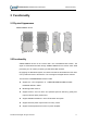

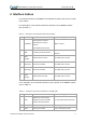

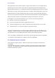
Table Of Contents

ZXSDR R8862A S7100 Product Description Internal Use Only▲
® Caltta Technologies. All rights reserved.
8
4 Interface Indices
The external interfaces of the R8862A are located at the bottom and on the front side
of the chassis.
For a description of the external interfaces at the bottom of the R8862A chassis,
refer to Table 4-1.
Table 4-1 Description of the External Interfaces at the Bottom
No. Label Interface Interface Type/Connector
1 AISG/MON
AISG equipment interface
MON external monitoring
interface
LMT O&M Ethernet interface
DB15 connector
2 GND Protective grounding interface
16 mm2 yellow-green round
terminal
3
ANT1
(TX/RX)
TX/RX antenna interface 50 Ω DIN-mode connector
4 ANT2 (RX) RX antenna interface 50 Ω DIN-mode connector
5 ANT3 (RX) RX antenna interface 50 Ω DIN-mode connector
6
ANT4
(TX/RX)
TX/RX antenna interface 50 Ω DIN-mode connector
For a description of the external interfaces on the right side of the R8862A chassis,
refer to Table 4-2.
Table 4-2 Description of the External Interfaces on the Right Side
No. Label Interface Interface Type/Connector
1 OPT1
Interface for communication
between the RRU and a BBU,
or RRU cascading interface
LC-type optical interface (IEC 874)
2 OPT2 RRU cascading interface LC-type optical interface (IEC 874)
3 PWR Power input interface 2-pin customized connector