
Instruction manual


99
5. THEORY OF OPERATION
5.1. GENERAL
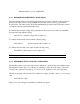
An explanation of the circuits within the AC Power System is given in this section. Refer to
Figure 5-1 for a block diagram of the AC Power System.
5.2. OVERALL DESCRIPTION
Input power from the rear panel is routed through an EMI filter, the circuit breaker, and to the
input transformer, T1. The input transformer provides three isolated six phase supplies each of
which are rectified to supply 300 VDC for the power amplifiers. A low power three phase
secondary provides isolated AC power to drive the oscillator and current limit boards and the two
fans on the lower front panel of the cabinet.
The oscillator assembly, A2, generates the oscillator waveforms and power source control and
measurement signals. The oscillator assembly plugs into the mother board, A6, through the
cabinet front panel.
The current limit assembly, A1, provides the programmable current limit function. The assembly
also generates the DC supplies for itself and the oscillator assembly using the isolated AC power
from T1.
The mother board, A6, makes the interconnections between the oscillator, current limit board,
power amplifiers, output sense, GPIB, and system interface.
The power amplifiers, A3, A4, A5, provide high power AC outputs using DC power from the
300 volt bus, and signal reference from the oscillator assembly.
One line of each of the outputs is routed through current transformers on A7, the current
transformer assembly; this is the means of measuring output current. Voltage sense is also
received from the sense terminal block and directed to the mother board.
The assemblies are described in more detail in the following paragraphs.
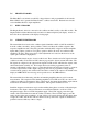
5.3. OSCILLATOR ASSEMBLY
The oscillator assembly, A2, consists of four printed circuit assemblies. These assemblies are
interconnected with a small mother board, A2A2. A block diagram of the oscillator assembly is
shown in Figure 5-2.