
Product Overview
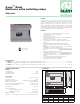

Boiler connections:
XX = Dry contact rated up to 120 VAC, 2 Amps,
which is typically connected to TT on boiler control,
closes when any zone calls including priority.
ZONE 1 E/S = Dry contact rated up to 120 VAC, 2 Amps, will close with
any call to ZONE 1. Zone 1 can be enabled as a priority zone, typically
used for heating domestic hot water. The ZONE 1 E/S can be used to
close a DHW contact on boiler controls equipped with these features.
AUX = Dry contact, rated up to 120 VAC, 2 Amps, close when any zone
calls and can be used as signal to a variable speed self regulated pump
or other controls.
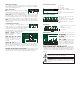
The ZVR series of controls is programmed by the dip switches which can
be positioned for the following operations.
Master / Slave: allows for
unlimited expansion to additional
ZVR or ZSR relays.
Pump Exercise ON / OFF:
When exercise mode is ON, each
circulator is switched on for 30
seconds following 72 hours of
inactivity.
Priority ON / OFF: When priority
switch is ON, upon demand, Zone 1 will operate as priority and all other
zones are temporarily switched off (with 1 hour time-out). When priority is
OFF, any zones that were active when Zone 1 was switched on will remain
on.
AUX ON / OFF Durning Priority Demand: When AUX switch is ON,
the AUX dry contacts will close during a priority demand. When switch is
OFF, the AUX dry contacts will remain open during a priority demand.
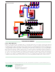
6 Zone
ZVR106
L
POWER IN
N
POWER
T-SAT
CALL
ZONE 6
L
ZONE #1
PUMP
N
L
SEC
PUMP
N
STATUS DURING
ZONE #1 DEMAND
ZONE 1
END
SWITCH
MOTOR
ZONE 2
END
SWITCH
MOTOR
ZONE 3
END
SWITCH
MOTOR
ZONE 4
END
SWITCH
MOTOR
ZONE 5
END
SWITCH
MOTOR
ZONE 6
END
SWITCH
MOTOR
L
SYSTEM
PUMP
N
T-STAT 2
C
R
W
T T COM
COMMS
D
P
ZONE 1
E / S
X X
T-STAT 3
C
R
W
T T COM
T-STAT 1
C
R
W
T T COM
T-STAT 4
C
R
W
T T COM
T-STAT 5
C
R
W
T T COM
T-STAT 6
C
R
W
T T COM
AUX
ON
OFF
ON
OFF
VALVE
OPEN
ZONE 1
ZONE 2
ZONE 4
ZONE 5
ZONE 3
MASTER
PUMP EXERCISE ON
PRIORITY ON
AUX ON
SLAVE
OFF
OFF
OFF
DURING PRIORITY DEMAND
Maintenance and Repair:
The Caleffi Z-one™ multi-zone valve relay comes with an automatic
resettable fuse and requires no maintenance. If control fails or is damaged,
replace control with functional one.
WARNING: NEVER CONNECT R & C DIRECTLY, this will
be a direct short on the 24 VAC supply.
WARNING: When connecting 2 or more Z-one controls,
all controls must be powered by the same 120 VAC
circuit.
L
PUMP 2
N
PRIMARY
PUMP
L
PRIORITY
PUMP 1
N
L
POWER IN
N
GROUNDS
L
PUMP 3
N
TRANSFORMER
L
N
L
PUMP 4
N
L
PUMP 5
N
L
PUMP 6
N
POWER
ZONE1
ZONE2
ZONE3
ZONE4
ZONE5
ZONE6
T-STAT 2
C
R
W
T T COM
COMMS
D
P
ZONE 1
E / S
X X
T-STAT 3
C
R
W
T T COM
T-STAT 1
C
R
W
T T COM
T-STAT 4
C
R
W
T T COM
T-STAT 5
C
R
W
T T COM
T-STAT 6
C
R
W
T T COM
AUX
6 Zone
ZSR106
MASTER
PRIORITY ON
REMOTE ENABLE ON
EXERCISE ON
POST PURGE ZONE#1 ON
SLAVE
OFF
OFF
OFF
OFF
REMOTE ENABLE
24 - 120 VAC
L
N
ON
OFF
STATUS
DURING
PRIORITY
Communication connections:
Connect terminals to matching terminal of slave
boards D to D, P to P, Ground to Ground. Use 18
gauge thermostat wire and it should be shielded if
located in close proximity to high voltage wiring.
L
PUMP 2
N
PRIMARY
PUMP
L
PRIORITY
PUMP 1
N
L
POWER IN
N
GROUNDS
L
PUMP 3
N
TRANSFORMER
L
N
L
PUMP 4
N
L
PUMP 5
N
L
PUMP 6
N
POWER
ZONE1
ZONE2
ZONE3
ZONE4
ZONE5
ZONE6
T-STAT 2
C
R
W
T T COM
COMMS
D
P
ZONE 1
E / S
X X
T-STAT 3
C
R
W
T T COM
T-STAT 1
C
R
W
T T COM
T-STAT 4
C
R
W
T T COM
T-STAT 5
C
R
W
T T COM
T-STAT 6
C
R
W
T T COM
AUX
6 Zone
ZSR106
MASTER
PRIORITY ON
REMOTE ENABLE ON
EXERCISE ON
POST PURGE ZONE#1 ON
SLAVE
OFF
OFF
OFF
OFF
REMOTE ENABLE
24 - 120 VAC
L
N
ON
OFF
STATUS
DURING
PRIORITY
SYSTEM PUMP = Runs when any
zone calls for heat.
SEC PUMP = Runs when any
zone calls for heat.
ZONE 1 PUMP = Runs when
zone 1 thermostat calls for heat
and zone 1 end switch has closed.
A jumper is required between the
ZONE 1 END SWITCH terminals
when using a pump for ZONE 1 instead of a zone valve.
STATUS DURING ZONE 1 DEMAND ON / OFF = When status
jumper is placed on ON pins, the secondary and / or system pump will
continue to operate during ZONE 1 demand. When jumper is placed
on OFF pins, the corresponding pump will be OFF during ZONE 1
demand.
L
PUMP 2
N
PRIMARY
PUMP
L
PRIORITY
PUMP 1
N
L
POWER IN
N
GROUNDS
L
PUMP 3
N
TRANSFORMER
L
N
L
PUMP 4
N
L
PUMP 5
N
L
PUMP 6
N
POWER
ZONE1
ZONE2
ZONE3
ZONE4
ZONE5
ZONE6
T-STAT 2
C
R
W
T T COM
COMMS
D
P
ZONE 1
E / S
X X
T-STAT 3
C
R
W
T T COM
T-STAT 1
C
R
W
T T COM
T-STAT 4
C
R
W
T T COM
T-STAT 5
C
R
W
T T COM
T-STAT 6
C
R
W
T T COM
AUX
6 Zone
ZSR106
MASTER
PRIORITY ON
REMOTE ENABLE ON
EXERCISE ON
POST PURGE ZONE#1 ON
SLAVE
OFF
OFF
OFF
OFF
REMOTE ENABLE
24 - 120 VAC
L
N
ON
OFF
STATUS
DURING
PRIORITY
R = 24 VAC.
W = Heat call
C = Common of 24 VAC
Heat demand is initiated by closing
R to W.
24 VAC is always present between
R & C.
Thermostat connections:
L
PUMP 2
N
PRIMARY
PUMP
L
PRIORITY
PUMP 1
N
L
POWER IN
N
GROUNDS
L
PUMP 3
N
TRANSFORMER
L
N
L
PUMP 4
N
L
PUMP 5
N
L
PUMP 6
N
POWER
ZONE1
ZONE2
ZONE3
ZONE4
ZONE5
ZONE6
T-STAT 2
C
R
W
T T COM
COMMS
D
P
ZONE 1
E / S
X X
T-STAT 3
C
R
W
T T COM
T-STAT 1
C
R
W
T T COM
T-STAT 4
C
R
W
T T COM
T-STAT 5
C
R
W
T T COM
T-STAT 6
C
R
W
T T COM
AUX
6 Zone
ZSR106
MASTER
PRIORITY ON
REMOTE ENABLE ON
EXERCISE ON
POST PURGE ZONE#1 ON
SLAVE
OFF
OFF
OFF
OFF
REMOTE ENABLE
24 - 120 VAC
L
N
ON
OFF
STATUS
DURING
PRIORITY
L = Line (hot leg) of 120 VAC
supply
N = Neutral of 120 VAC
= Grounds
Input power:
Pump outputs:
6 Zone
ZVR106
L
POWER IN
N
POWER
T-SAT
CALL
ZONE 6
L
ZONE #1
PUMP
N
L
SEC
PUMP
N
STATUS DURING
ZONE #1 DEMAND
ZONE 1
END
SWITCH
MOTOR
ZONE 2
END
SWITCH
MOTOR
ZONE 3
END
SWITCH
MOTOR
ZONE 4
END
SWITCH
MOTOR
ZONE 5
END
SWITCH
MOTOR
ZONE 6
END
SWITCH
MOTOR
L
SYSTEM
PUMP
N
T-STAT 2
C
R
W
T T COM
COMMS
D
P
ZONE 1
E / S
X X
T-STAT 3
C
R
W
T T COM
T-STAT 1
C
R
W
T T COM
T-STAT 4
C
R
W
T T COM
T-STAT 5
C
R
W
T T COM
T-STAT 6
C
R
W
T T COM
AUX
ON
OFF
ON
OFF
VALVE
OPEN
ZONE 1
ZONE 2
ZONE 4
ZONE 5
ZONE 3
MASTER
PUMP EXERCISE ON
PRIORITY ON
AUX ON
SLAVE
OFF
OFF
OFF
DURING PRIORITY DEMAND
Motor = 24 VAC to power the
zone valve motor
End Switch = Connects to end
switch on zone valve. Must be
jumpered if using a 2 –wire zone
valve.
Zone valve connections: