NA10331 www.caleffi.com Zone Control Relay © Copyright 2013 Caleffi Function ZSR101 Series The ZSR101 single zone switching relay is operated by low voltage thermostats. The ZSR101 single zone switching relay incorporates Power In, Relay 1 and Relay 2 connection terminals to provide a convenient and cost effective way to control a circulator and a boiler operating control in a single zone hydronic heating system.
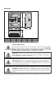
Dimensions ZSR101 PWR CAUTION: RISK OF ELECTRIC SHOCK - DISCONNECT ALL INPUT POWER PRIOR TO SERVICING ZONE ZSR101 Single DPDT relay - Input: 120VAC 50/60Hz 10A MAX Single DPDT relay 4009064 Conforms to UL 873 A Milwaukee, WI 53208 USA B C C Code ZSR101 Zones 1 A 5 3/8" B 4 5/8" C 2 5/8" Wgt. (lbs) 1.1 SAFETY INSTRUCTION This safety alert symbol will be used in this manual to draw attention to safety related instructions.
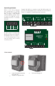
T When a zone has a demand from a thermostat (T T or R W) the relay will close sending 120 VAC to Relay 1 NO terminal switching ON the pump, Relay 2 closes C to NO dry contact, signaling the boiler of a heating demand. R W C T T COM 1 Zone Supply 120 VAC hot to termilan L and 120 VAC neutral to N. A factory installed jumper from L terminal to the C terminal of Relay 1 is supplied for simplified pump connection. R, W, C and T T Comm dual labeling at thermostat terminals.
Installation • • FUSE FUSE The unit must be only located in dry interior locations. It is not suitable for installation in hazardous locations and should not be placed close to any electromagnetic fields. Please pay attention to routing of power supply cables. • • • • Remove cover of relay box. Identify the four mounting holes on relay box, mark on the wall the desired location of mounting. Predrill, anchor, and fasten four screws for mounting. Hang relay box and fasten tight to desired locations.
WIRING GUIDE The ZSR101 is a versatile single relay control with two outputs for operating a 120 VAC pump with boiler enable, or two 120 VAC devices without boiler enable. Features include rear knock outs for 4x4 junction box mounting, convenient pre-installed jumper for pump operation, and 10 amp total load rating. The ZSR Series of controls is for zoning using pumps. Up to 6 zone pumps (model dependent) along with a primary pump can be operated. Zone priority is selectable with 1-hour time-out feature.
2
INDEX Z-one Relay thermostat connections Thermostat wiring............................................................................................................................................................................ 3 ZSR101 - single zone relay Product overview............................................................................................................................................................................. 4 Operation and cover removal ................................
Z-one Thermostat Connections 2-Wire Thermostats 4-Wire Thermostats All Caleffi Z-one controls use the same interface to connect to thermostats. This interface is very flexible and allows many different types of thermostats to be connected to the control including 2, 3 and 4 wire versions. In addition, any type of switching device can be used to signal a heat demand by connecting the R & W (T & T) terminals together. The terminals are dual labeled to help simplify wiring.
Wiring of 2 wire or 3 zone valve to Caleffi Z-one Relay Wiring a 2 wire zone valve to Caleffi Z-one Relay Wiring a 3 wire zone valve to Caleffi Z-one Relay Since a two wire actuator does not have an end switch for feedback to the relay box, the end switch terminals must have a jumper to DHW R end R R is not R W C W C W Cinstalled, W no C simulate X the swith. If the switch jumper X end ZR/ZC T T COM T T COM T T COM T T COM demand will be sent to the T-STAT boiler and the pumps will not on4.
6 ZSR101 - Single Zone Switching Relay 4009064 Certified to CSA C22-2 No.
Operating Principles When a zone has a demand from a thermostat (TT or R W) the relay will close sending 120 VAC to Relay #1 NO terminal R W and switching the pump R TW C T on, and the C to NO dry T T COM contact on relay #2 closes, signaling the boiler of a heating demand. Dual labeled T-stat terminals. Compatible with 2, 3 and 4 wire T-stats. Replaceable fuses. 6 VA Transformer. C COM PWR R, W, C and T T Comm dual labeling at thermostat terminals.
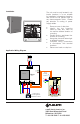
8 A1 - Single thermostat R T W C T com power zone transformer N L Caleffi! single zone relay RELAY 1 RELAY 2 C N/O N/C C N/O N/C N L Hydronic diagram is for illustration purposes only, some components have been removed for simplicity.
Description of terminals Sequence of Operation / Settings = Ground • A demand occurs and closes RW (TT) N = Neutral (Common leg of 120 VAC) • L = Line (live leg of 120 VAC) Relay #1 and relay #2 both fire connecting the common terminal to the NO terminal. C = Common terminal • NO = Normally Open terminal NC = Normally Closed terminal If the factory installed jumper has not been removed, the NO terminal of relay #1 will deliver the hot leg of 120 VAC. Relay #2 has dry contacts.
10 A2 - Multiple thermostats power zone transformer N L R Caleffi! single zone relay RELAY 1 RELAY 2 C N/O N/C C N/O N/C N L Hydronic diagram is for illustration purposes only and could be missing system components.
Description of terminals = Ground Sequence of Operation / Settings • There is a demand by one of the t-stats which sends power to the corresponding zone valve. • When the zone valve opens, its end switch contacts close and signal a demand to the RW (TT) contacts on the single zone relay control.
12 A3 - Single master thermostat, panel radiators with TRVs, variable speed pump TRV TRV thermostatic! radiator valves! (TRV) on each! radiator TRV TRV TRV TRV R W C T T com buffer tank power zone transformer NL N L Hydronic diagram is for illustration purposes only, some components have been removed for simplicity.
Description of terminals = Ground N = Neutral (Common leg of 120 VAC) L = Line (live leg of 120 VAC) C = Common terminal NO = Normally Open terminal NC = Normally Closed terminal Note: There is a factory installed jumper between the 120 VAC line (L) and the common terminal of relay #1 (C). Sequence of Operation / Settings • • When the temperature drops below the thermostat’s set point, a heat demand is initiated by closing the R & W terminals. • Relay #1 and relay #2 both fire.
14 ZSR10X - Multi-Zone Pump Control 4009064 Certified to CSA C22-2 No.
XX Closes for heat demand and DHW demand. Rated for 120 VAC, 2 amps. DHW (ZR/ZC) closes only during priority call. Rated for 120 VAC, 2 amps. Dual labeled T-stat terminals. Compatible with 2, 3 and 4 wire T-stats. Selectable DIP switches. 3 wire communications to expansion board. Power ON LED. LED for each zone. 120 VAC input power connection Multiple ground connections for easy wiring. Replaceable fuses (2 extra included under cover). 120 VAC zone pump outputs. 120 VAC primary pump output.
16 Cover removal Hold either the left or the right end of the box up and at an angle. Use body for stabilizing relay box. Insert screwdriver and push tab inward, cover should release from base. Mounting: Do not mount to a surface that exceeds 115°F (45°C). The unit must be only located in dry interior locations. Use only copper conductor supply wire suitable for at least 105° C. All circuits must have a common disconnect and be connected to the same pole of the disconnect.
DHW R R R R R R D W C P W C C W C DIP Switches on theWZSRCseries W C Maintenance and Repair: The X Caleffi Z-one™ multi-zone pump control W The X ZR/ZC COMMS T COM T T COM T T COM T T COM T T COM T T COM T can be positioned for the following DipSwitches comes with two spare fuses. If control fails or is damaged, replace control with T-STAT 6 Slave T-STAT 1 T-STAT 2 T-STAT 3 T-STAT 4 T-STAT 5 operations. Master functional one.
18 Pump 4 Pump 3 Pump 1 Pump 2 B1 - Mod/con boiler, hydro separator or buffer tank, zone pumps Buffer tank- Optional hydraulic separator XX DHW R ZR/ZC T W R C T COM T T-STAT 1 W C T COM T-STAT 2 R T W C T COM T-STAT 3 R T W C T COM T-STAT 4 R W T C T COM T-STAT 5 R T W C D P COMMS T COM PWR T-STAT 6 ZONE1 ZONE2 6 Zone ZSR106 TRANSFORMER DipSwitches Master Priority OFF Primary OFF Exercise OFF Post Purge OFF ZONE3 Slave Priority ON Primary ON Exercise ON Po
Description of terminals N L Sequence of Operation / Settings = Ground Priority switch: OFF = Neutral (Common leg of 120 VAC) = Line (Hot leg of 120 VAC) Master / Slave switch: Master Thermostat terminals R = 24 VAC W = Heat call C = Common of 24 VAC Boiler terminals XX = Dry contacts rated up to 120 VAC, 2 Amps. Closes when any zone calls including priority. Typically connected to TT on boiler control. DHW (ZR/ZC) = Dry contacts rated up to 120 VAC, 2 Amps.
20 Pump 6 Pump 5 Pump 1 boiler! high limit! control Pump 4 Pump 2 Pump 3 B2 - Traditional boiler, indirect DHW w/ priority, zone pumps DHW! aquastat DHW! aquastat XX DHW R ZR/ZC T W R C T COM T THM 1 W R C T COM THM 2 W T R C T COM T THM 3 W C T COM THM 4 R W T R C W T T COM D C T COM P COMMS PWR THM 6 THM 5 ZONE1 ZONE2 6 Zone Z6P ZSR106 TRANSFORMER 12/20VA TT ZC ZR DipSwitches Master Priority OFF Primary OFF Exercise OFF Post Purge OFF ZONE3 Slave
Description of terminals N L Sequence of Operation / Settings = Ground Priority switch: ON (Zone #1 becomes priority) = Neutral (Common leg of 120 VAC) = Line (Hot leg of 120 VAC) Master/Slave switch: Master Thermostat terminals R = 24 VAC W = Heat call C = Common of 24 VAC Primary Status During Priority switch: OFF • A demand occurs from a T-stat (T-stat closes TT terminals) in zones 2 thru 6. • The “PUMP ON” LED illuminates for that zone.
22 Pump 3 Pump 1 Pump 2 B3 - Mod/Con boiler, primary loop, closely spaced tees, zone pumps boiler pump Primary pump XX DHW R ZR/ZC T W R C T COM T T-STAT 1 W C T COM T-STAT 2 R T W C T COM T-STAT 3 R T W C T COM T-STAT 4 R W T C T COM T-STAT 5 R T W C D P COMMS T COM PWR T-STAT 6 ZONE1 ZONE2 36 Zone ZSR106 3 TRANSFORMER DipSwitches Master Priority OFF Primary OFF Exercise OFF Post Purge OFF ZONE3 Slave Priority ON Primary ON Exercise ON Post Purge ON ZONE4
Description of terminals N L Sequence of Operation / Settings = Ground Priority switch OFF = Neutral (Common leg of 120 VAC) = Line (Hot leg of 120 VAC) Master / Slave switch: Master Thermostat terminals R = 24 VAC W = Heat call C = Common of 24 VAC Boiler terminals XX = Dry contacts rated up to 120 VAC, 2 Amps. Closes when any zone calls including priority. Typically connected to TT on boiler control. DHW (ZR/ZC) = Dry contacts rated up to 120 VAC, 2 Amps.
24 ZVR10X - Multi-Zone Valve Control 4009064 Certified to CSA C22-2 No.
XX Closes for heat demand and DHW demand. Rated for 120 VAC 2 amps. DHW (ZR/ZC) closes only during priority call. Rated for 120 VAC, 2 amps. Dual labeled T-stat terminals. Compatible with 2, 3 and 4 wire T-stats. Master/Slave jumper. 3 wire communications to expansion board. Power ON LED. Transformer connections. LED illuminates when end switch closes. 120 VAC input power connection. 120 VAC output to pumps. System pump (boiler pump) status during priority can be changed with jumper.
Cover removal Hold either the left or the right end of the box up and at an angle. Use body for stabilizing relay box. 26 Insert screwdriver and push tab inward, cover should release from base. Roll cover off base. Remove transformer(s) packaging. Slide bottom end of transformer into bottom latch. Transformer Installation Mount box on stable surface using level. from Snap top of transformer into latch arms. Mounting: Do not mount to a surface that exceeds 115°F (45°C).
T-STAT 1 DHW XX R W C R W T-STAT 2 C ZR/ZC T T COM T T COM Maintenance and Repair: The Caleffi Z-one™ multi-zone valve relay comes with T-STAT 1 T-STAT 2 a resettable fuse and requires no maintenance. If control fails or is damaged, replace control with functional one. R T 6 Zone W R C T-STAT 4 W T-STAT 5 R C T COM T T COM Thermostat connections T-STAT 3 ZVR106 DHW T-STAT 3 DHW T-STAT 4 T SLAVE C T COM R W T MASTER C TSAT2 T COM SLAVE T-STAT 6 T-STAT 5 R = 24 VAC.
28 C1 - Mod/Con boiler, hydro separator, zone valves mod/con! boiler ZV1 PRIORITY! SYSTEM ZV2 ZV3 ZV4 ZV5 ZV6 SECONDARY! pump pump XX DHW R ZR/ZC T W R C T COM W T T-STAT 1 R C T COM T-STAT 2 T W C T COM T-STAT 3 R T W C T COM T-STAT 4 R T W C T COM T-STAT 5 R T W D C P PWR COMMS T COM T-STAT 6 TSAT1 ZONE1 MASTER SLAVE TSAT2 ZONE2 ZVR106 TSAT3 ZONE3 6 Zone STATUS DURING PRIORITY ON OFF TSAT5 ZONE5 PRIORITY ON POWER IN L N PRIORITY PUMP N L SEC P
Description of terminals Sequence of Operation / Settings = Ground Priority Jumper: OFF N = Neutral (common leg of 120 VAC) Master / Slave Jumper: Master L = Line (live leg of 120 VAC) Status During Priority: OFF Thermostat terminals R = 24 VAC W = Heat call C = Common of 24 VAC Boiler terminals XX = Dry contacts rated up to 120 VAC, 2 Amps. Closes when any zone calls including priority. Typically connected to TT on boiler control. DHW (ZR/ZC) = Dry contacts rated up to 120 VAC, 2 Amps.
30 C2 - Mod/Con boiler, priority indirect DHW on primary side of hydro sep, zone valves mod/con! boiler ZV2 ZV3 ZV4 ZV5 ZV6 DHW! aquastat PRIORITY! pump SECONDARY! pump SYSTEM! pump DHW! AQUASTAT XX DHW R ZR/ZC T W R C T COM W T T-STAT 1 R C T COM T-STAT 2 T W C T COM T-STAT 3 R W T C T COM T-STAT 4 R T W C T COM T-STAT 5 R T W D C P PWR COMMS T COM T-STAT 6 TSAT1 ZONE1 MASTER SLAVE TSAT2 ZONE2 ZVR106 TSAT3 ZONE3 6 Zone STATUS DURING PRIORITY ON OFF
Description of terminals = Ground Sequence of Operation / Settings • The XX and DHW contacts close. • The PRIORITY PUMP contacts deliver 120 VAC Status During Priority: OFF • The SEC PUMP and SYSTEM PUMP are off. • A demand occurs from a T-stat (T-stat closes TT terminals) in zones 2 thru 6. The “T-STAT CALL” LED illuminates for that zone. • Once the Zone #1 DHW demand is satisfied, power to the PRIORITY PUMP is dropped, the DHW contacts open.
32 C3 - Mod/Con boiler, priority indirect DHW on load side of hydro sep, zone valves Buffer tank- Optional hydraulic separator ZV2 SECONDARY! pump SYSTEM! pump PRIORITY! pump DHW! AQUASTAT DHW! AQUASTAT XX DHW R ZR/ZC T W R C T COM W T T-STAT 1 R C T COM T-STAT 2 T W C T COM T-STAT 3 R T W C T COM T-STAT 4 R T W C T COM T-STAT 5 R T W D C P PWR COMMS T COM T-STAT 6 TSAT1 ZONE1 MASTER SLAVE TSAT2 ZONE2 ZVR106 TSAT3 ZONE3 6 Zone STATUS DURING PRIORITY ON O
Description of terminals Sequence of Operation / Settings = Ground Priority Jumper: ON (Zone #1 becomes priority) N = Neutral (common leg of 120 VAC) Master/Slave Jumper: Master L = Line (live leg of 120 VAC) Status During Priority: ON Thermostat terminals R = 24 VAC W = Heat call C = Common of 24 VAC Boiler terminals XX = Dry contacts rated up to 120 VAC, 2 Amps. Closes when any zone calls including priority. Typically connected to TT on boiler control.
34 C4- Mod/Con boiler, priority indirect DHW on primary side of hydro sep, expansion control Buffer tank - Optional hydraulic separator ZV2 ZV3 ZV4 ZV8 ZV7 ZV6 ZV5 ZV9 ZV12 ZV11 ZV10 SECONDARY! pump PRIORITY! pump DHW! AQUASTAT SYSTEM! pump DHW! AQUASTAT XX DHW R ZR/ZC T W R C T COM W T T-STAT 1 R C T COM T-STAT 2 T W C T COM T-STAT 3 R W T C T COM T-STAT 4 R T W C T COM T-STAT 5 R T W D C P XX PWR COMMS T COM DHW R ZR/ZC T T-STAT 6 W R C T
Description of terminals Sequence of Operation / Settings = Ground Control #1 (Master) N = Neutral (common leg of 120 VAC) Priority Jumper: ON (Zone #1 becomes priority) L = Line (live leg of 120 VAC) Master/Slave Jumper: Master Thermostat terminals R = 24 VAC W = Heat call C = Common of 24 VAC Boiler terminals XX = Dry contacts rated up to 120 VAC, 2 Amps. Closes when any zone calls including priority. Typically connected to TT on boiler control.
36 ZV6 ZV5 ZV4 SYSTEM! pump ZV3 ZV2 C5 - Traditional boiler, indirect DHW (no priority) with valve, zone valves ZV1 DHW! aquastat XX DHW R ZR/ZC T W R C T COM THM 1 W T R C T COM THM 2 T W C T COM THM 3 R W T C T COM THM 4 R T W C T COM THM 5 R T W C D P PWR COMMS T COM THM 6 Master/Slave ZRV106 6 Zone Z6V THM1 ZONE1 THM2 ZONE2 THM3 ZONE3 THM4 ZONE4 THM5 ZONE5 STATUS DURING PRIORITY POWER IN L N PRIORITY PUMP L N SEC PUMP L L N Hydronic diagram is
Description of terminals Sequence of Operation / Settings = Ground Priority Jumper: OFF N = Neutral (common leg of 120 VAC) Master/Slave Jumper: Master L = Line (live leg of 120 VAC) Status During Priority: OFF Thermostat terminals R = 24 VAC W = Heat call C = Common of 24 VAC • A demand occurs from a T-stat (T-stat closes TT terminals) in zones 2 thru 6 otr the aquastat on zone #1. The “T-STAT CALL” LED illuminates for that zone. Boiler terminals XX = Dry contacts rated up to 120 VAC, 2 Amps.
ZV6 ZV5 ZV4 SYSTEM! pump ZV3 ZV2 C6- Traditional boiler with reset control, priority indirect DHW with valve, zone valves ZV1 DHW! aquastat DHW! aquastat XX DHW R ZR/ZC T W R C T COM THM 1 W T R C T COM THM 2 T W C T COM THM 3 R W T C T COM THM 4 R T W C T COM THM 5 R T W C D P Master/Slave ZRV106 6 Zone Z6V ZC ZR T T PWR COMMS T COM THM 6 THM1 ZONE1 THM2 ZONE2 THM3 ZONE3 THM4 ZONE4 THM5 ZONE5 STATUS DURING PRIORITY POWER IN L N PRIORITY PUMP L N SE
Description of terminals Sequence of Operation = Ground Priority Jumper: ON (Zone #1 becomes priority) N = Neutral (common leg of 120 VAC) Master/Slave Jumper: Master L = Line (live leg of 120 VAC) Status During Priority: ON Thermostat terminals R = 24 VAC W = Heat call C = Common of 24 VAC Boiler terminals XX = Dry contacts rated up to 120 VAC, 2 Amps. Closes when any zone calls including priority. Typically connected to TT on boiler control.
C7 - Mod/Con boiler, hydro separator, zone valves (more than 6), multiple secondary pumps 40 "B"! pump "A"! pump A7 A8 A9 A10 A11A12 A1 A2 A3 A4 A5 A6 SYSTEM! pump XX DHW R ZR/ZC T W R C T COM W T T-STAT 1 R C T COM T-STAT 2 W T C T COM T-STAT 3 R W T C T COM T-STAT 4 R T W C T COM T-STAT 5 R T W D C P XX PWR COMMS T COM DHW R ZR/ZC T T-STAT 6 W R C T COM W T T-STAT 1 R C T COM T-STAT 2 W T C T COM T-STAT 3 R W T C T COM T-STAT 4 R T
Description of terminals Sequence of Operation / Settings = Ground Control #1 (Master) N = Neutral (common leg of 120 VAC) Priority Jumper: OFF L = Line (live leg of 120 VAC) Master/Slave Jumper: Master Thermostat terminals R = 24 VAC W = Heat call C = Common of 24 VAC Status During Priority: OFF Boiler terminals XX = Dry contacts rated up to 120 VAC, 2 Amps. Closes when any zone calls including priority. Typically connected to TT on boiler control.
42 Caleffi North America, Inc. / 3883 W Milwaukee Rd / Milwaukee, WI 53208 Tel: 414.238.2360 / Fax: 44.238.2366 www.caleffi.com/usa / sales@caleffi.