
Product Overview
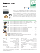
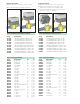

Flow characteristics
Connection size Flow coefficient Max. Close-off DP
1/2” 1.0 Cv (0.9 Kv) 75 psi (517 kPa)
1/2” - 3/4” 2.5 Cv (2.2 Kv) 50 psi (345 kPa)
1/2” - 3/4” 3.5 Cv (3.0 Kv) 30 psi (207 kPa)
3/4” - 1” 5.0 Cv (4.3 Kv) 25 psi (172 kPa)
3/4” - 1” - 1 1/4” 7.5 Cv (6.5 Kv) 20 psi (138 kPa)
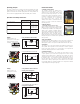
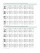
(psid) (kPa)
5.0 Cv
4.3 Kv
3/4”
1”
2.5 Cv
2.2 Kv
1/2”
3/4”
1.0 Cv
0.9 Kv
1/2”
5
00
2
00
1000
∆
P (psid)
G (l/h) (
gpm
)
0.1
1
0.2
0.3
0.5
2
3
5
1
0
.5
10
2
5
2
0
1
10
2
3
5
20
30
0.4
4
0.1
1
0.2
0.3
0.5
2
3
5
0.4
4
4000
2000
3.5 Cv
3.0 Kv
1/2”
3/4”
7.5 Cv
6.5 Kv
3/4”-1”
-1 1/4”
Hydraulic characteristics
Installation
- The valve can be installed either vertically or horizontally, with the
actuator in any position, except upside down.
-
If it is installed inside an enclosure it is important to ensure that there
is adequate ventilation inside the enclosure itself.
-
The three-way valve cannot be transformed into a two-way valve
and vice versa.
- When zone valves are installed, the direction of flow must be
observed.
- Two-way zone valves can be installed either in the supply or return
piping; the direction of flow indicated by the arrow on the body of
the valve must be observed.
- Three-way zone valves use the normally closed actuator only (rotate
180° the valve body for normally open application).
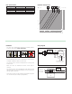
360°
BA
AB
(
NA
)(
NC
)
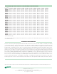
To relay, boiler contacts
(TT) or DDC system
Thermostat
Motor
L1 (HOT)
L2
Black
Black
Red Red
Auxiliar y Switch
Wiring diagram
Terminal block
To relay, boiler
contacts (TT)
or DDC system.
Thermostat
L1 (HOT)
L2
24 V
only