
Install Instructions
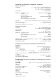

Size
1”
1 1/4” 1 1/2”
2”
2”
2 1/2”
3” 4” 5” 6” 8” 10” 12”
gpm
11 18 26 37 60 80 124 247 300 484 792 1330 1850
m
3
/h
2.5 4 68.4 13.6 18 28 56 68 110 180 302 420
UNION FLANGED
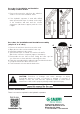
Installation
The installation of hydraulic separator should only be done by qualified
personnel in accordance with current legislation.
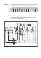
The hydraulic separator is installed between the primary and secondary
circuits, always in a vertical position.
Hydraulic
characteristics
The hydraulic separator should be sized according to the maximum flow
rate value foreseen at the inlet. The selected value must be either that of
the primary circuit or of the secondary, whichever is the greatest.
14”
2500
568