
Product Overview

CALEFFI
Hydro Separator
NA548 ASME & CRN Series with Flanged Connections, 2”– 4”
Submittal Data 02910 — Issue Date 09/2014
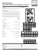
Dimensions
Job name ______________________________________
Job location ______________________________________
Engineer ______________________________________
Mechanical contractor ________________________________
Contractor’s P.O. No. ________________________________
Representative ________________________________
Size ________________________________________
Quantity ________________________________________
Approval ________________________________________
Service ________________________________________
Tag No. ________________________________________
Notes ________________________________________
Caleffi North America, Inc. 3883 West Milwaukee Road / Milwaukee, WI 53208
Tel: 414.238.2360 / Fax: 414.238.2366 / www.caleffi .us
© Copyright 2014 Caleffi
Hydraulic Characteristics
Application
Technical Data
Materials:
- Body: epoxy resin painted steel
- Internal baffl e: 300 series stainless steel
- Drain and shut-off valve body: brass
- Air vent body: brass
Suitable fl uids: water, or 50% max. glycol solution
Max working pressure: 150 psi (10 bar)
Vessel working temperature range:
- with insulation: 32-220°F (0-105°C)
- without insulation: 32-270°F (0-132°C)
Connections:
- Flanged: (ASME & CRN Registered) 2 “ - 4” ANSI B 16.5 Class 150 RF
- Drain valve: 1 1/4” FNPT
Insulation:
Material: rigid closed cell expanded polyurethane foam
Thickness: 2 3/8” (60 mm)
Density: 2.8 lb/ft (45 kg/m³)
Thermal conductivity: 6 BTU
.
in/hr
.
ft²
.
°F (0.023 W/(m
.
K))
Temperature range: 32-220° F (0 – 105°C)
External cover:
Material: embossed aluminium
Thickness: 7.0-mil (0.7 mm)
Reaction to fi re (DIN 4102): class 1
Head covers: Heat molded material: PS
F
B
C D E
H
HYDRO SEPARATOR
Serie 548
T
max
120∞C
P
max
10 bar
T
max
105∞C
P
max
10 bar
A
G
A
I
The hydraulic separator should be sized according to the maximum fl ow
rate at the inlet. The selected design value must be the greatest between
the primary circuit and the secondary circuit.
Code A B C D E F
NA548052A 2” 1-1/4” 13” 13” 15” 14”
NA548062A 2-1/2” 1-1/4” 13” 13” 15” 14”
NA548082A 3” 1-1/4” 15” 17-3/4” 17” 18”
NA548102A 4” 1-1/4” 15” 17-3/4” 17” 18”
Flow Capacity
Size 2” 2-1/2” 3” 4”
gpm 60.0 80.0 124.0 247.0
I/sec. 3.8 5.0 7.8 15.6
Code Weight
(lb)
Weight
(kg)
Flow
(gpm)
Flow
(I/sec.)
Volume
(gal)
Volume
(I)
NA548052A 75.0 33.1 60.0 3.8 4.0 15.1
NA548062A 82.0 35.8 80.0 5.0 4.0 15.1
NA548082A 112.0 49.0 124.0 7.8 8.0 30.3
NA548102A 117.0 53.1 247.0 15.6 8.0 30.3
Code G H I
NA548052A 6-5/8” 6” 0.88”
NA548062A 6-5/8” 7” 0.94”
NA548082A 8-5/8” 7.5” 1”
NA548102A 8-5/8” 9” 1.19”
Typical Specification
Furnish and install on the plans and described herein, a Caleffi Hydro Separator as
manufactured by Caleffi. Each separator must be designed with an epoxy resin
painted steel body, 300 series stainless steel internal baffle, preformed insulation,
a brass blowdown drain valve and automatic brass air vent isolated manually with
brass shutoff valve. The separator design must include ANSI B16.5 Class 150 RF
flanges. The separator must be designed and built in accordance with Section VIII,
Div. 1 of the ASME Boiler and Pressure Vessel Code and tagged and registered
with the National Board of Boiler and Pressure Vessel inspector, CRN Registered,
and stamped for 150 psi (10 bar) working pressure, with ASME U stamp. Each
separator shall be Caleffi model NA548 series or approved equal. (See product
instructions for specific installation information.)
We reserve the right to change our products and their relevant technical data, contained in this publication, at any time and without prior notice. Contractors should request production drawings if prefabricating the system.
The hydraulic separator creates a zone with a low pressure loss, which enables the
primary and secondary circuits connected to it to be hydraulically independent of
each other; the fl ow in one circuit does not create a fl ow in the other.