
Brochure


Installation
The dirt separator should be installed in accordance with the fl ow
direction indicated by the arrow on the tee fi tting and the return circuit
upstream of the boiler.
The dirt separator should always be installed upstream of the pump
and always with its body in vertical position.
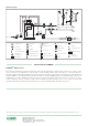
Hydraulic characteristics
1 2 3 4 5 6 7 8 9 10 20 30 40 50
.1
.2
.3
.4
.5
.6
.7
.8
.9
1
.23
.3
.4
.5
.6
.7
.8
.9
1
1.2
1.4
1.6
1.8
2
2.3
ft. of hdpsid
gpm
.06 .08 .1 .12 .14.16.18.2 .3 .4 .5 .6 .7 .8 .9 2 1.5 2 2.5 3
l/s
.69
.8
.9
1
1.2
1.4
1.6
1.8
2
2.2
2.4
2.6
2.8
3
3.5
4
4.5
5
5.5
6
6.9
kPa
3/4”
∆ P ∆ P
ow rate
1”
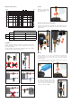
Maintenance
Air vent
Eliminate air collected in the
top of the body by loosening
the top plug screw.
To perform maintenance after isolating
the separator, simply unscrew the
top cover using the provided key and
remove the attached internal element
inside the collection chamber.
Draining off dirt and ferrous impurities
Remove the magnetic ring (1) and drain the collected dirt and ferrous
impurities. This can be done while the system is running, using the
key provided (2).
1
2
This multifunction device can also be used as a dosing point to inject
chemical additives into the circuit. Codes NA545355 and NA545356
offer integral isolation check valves making for a more convenient dosing
vessal, providing an easy access point for routine system water treatment
in hydronic systems.
Use a screwdriver to undo the screw on the top plug in order to purge any
air that has collected at the top of the body.
Dosing
FLOW RATE
Size ¾" 1"
4.0 f/s
GPM 8 9
10.0 f/s
GPM 14 20
Cv 12 19