
Solar Thermal Information


7
The following guidelines are suggested in applications
where a heated floor slab will be used to deliver heat
derived from a solar collector array:
• Tube spacing within the slab should not exceed 12
inches
• Slab should have minimum of R-10 underside
insulation
• Tubing should be placed at approximately 1/2 the slab
depth below the surface, as shown in figure 3-2
• Bare, painted or stained slab surfaces are ideal because
the finish floor resistance is essentially zero
• Other floor finishes should have a Total R-value of 1.0
or less
HEATED THIN-SLABS:
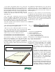
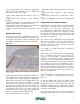
Another common method of installing floor heating uses
a “thin slab” (1.5-inch to 2-inch thickness) poured over a
wooden floor deck. Figure 3-3 shows an example of such
an installation, awaiting placement of the slab material.
Courtesy of H. Youker
Because the slab is thinner than with slab-on-grade floors,
it has slightly lower lateral heat dispersal characteristics.
This translates into a slightly higher water temperature
requirement for a given rate of heat output relative to that
required for a slab-on-grade. This difference is slight.
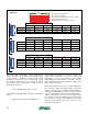
A 1.5-inch-thick concrete thin slab with 12-inch tube
spacing and covered with a finish flooring resistance of
0.5ºF•hr•ft
2
/Btu yields about 8% less heat output than
a 4-inch-thick slab with the same tube spacing and
finishing flooring. This can be easily compensated for by
using 9-inch rather than 12-inch tube spacing.
The following guidelines are suggested:
• Tube spacing within the thin slab should not exceed 9
inches
• Slab should have minimum of R-19 underside
insulation
• Floor finishes should have a total R-value of 1.0 or
less
• Never use “lightweight” concrete for heated thin slabs
OTHER SITE-BUILT RADIANT PANELS:
Radiant panels can be integrated into walls and ceilings
as well as floors. Several of these configurations may
be suitable for use with solar combisystems. The
key is ensuring the radiant panel can deliver design
load output while operating at a relatively low water
temperature. This helps ensure the solar collectors will
also operate at a relatively low fluid temperature and
reasonably good efficiency.
This criterion favors radiant panels that provide high
surface areas relative to the rate of heat delivery. It
also favors panels that have relatively low internal
resistance between the tubing and the surface area
releasing heat to the room.
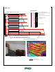
One example is a radiant wall panel constructed as
shown in figure 3-4.
When finished, this “radiant wall” is indistinguishable
from a standard interior wall. Its low thermal mass
allows it to respond quickly to changing internal load
conditions or zone setback schedules. The rate of heat
emission to the room is approximately 0.8 Btu/hr/ft
2
for
each degree Fahrenheit the average water temperature
in the tubing exceeds room air temperature. Thus, if
the wall operates with an average water temperature of
110ºF in a room with 70ºF air temperature, each square
foot of wall would release about 0.8 x (110 - 70) = 32
Btu/hr/ft
2
. This performance makes it well suited for use
with a solar combisystem.
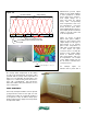
Another possibility is a radiant ceiling using the same
type of construction as the radiant wall, as shown in
figure 3-5.
As with the radiant wall system, this radiant ceiling
has low thermal mass and responds quickly to interior
temperature changes. Heated ceilings also have the
advantage of not being covered or blocked by coverings
or furniture, and thus are likely to retain good performance
over the life of the building.
For the construction shown, the rate of heat emission is
approximately 0.71 Btu/hr/ft
2
for each degree Fahrenheit
figure 3-3