
Solar Thermal Information


67
Energy meter
WMZ-G1
Function
Product range
Technical specifications
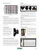
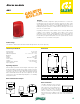
System diagram
CALEFFI
DataLogger
The connection sequence is arbitrary, up to 16 can be cascaded together
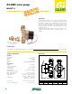
WMZ-G1 Calorimeter module for Grundfos Direct Sensors™
Article-no: 135 307 03
Grundfos Direct Sensor™ VFS 1-12 or 20? l Sensor incl. brass fitting, insert and connection
cable
Article-no: 130 000 20
Grundfos Direct Sensor™ VFS 2-40 l Sensor incl. brass fitting, insert and connection cable
Article-no: 130 000 30
Grundfos Direct Sensor™ RPS 0-10 bar Sensor incl. brass fitting and connection cable
Article-no: 130 000 40
The WMZ-G1 is an energy meter for thermal solar systems and conventional
heating systems. The WMZ-G1 calculates energy by integrating flow rate and
temperature from a Vortex Flow Sensor (VFS) Grundfos Direct Sensors
™ and
temperature difference in the flow and return piping using a Relative Pressure
Sensor (RPS) Grundfos Direct Sensors
™. The calculated heat energy value is
displayed in kWh (kilowatt hours) and stored. A power failure protection guaran-
tees that the adjusted system parameters and the calculated heat energy
quantity are maintained in the case of power loss.
Grundfos Direct Sensors
™
Technology
The VFS combines the established vortex principle with the direct exposure of
the sensor chip to the media gives a superior sensitivity and fast response. The
VFS sensor detects the pressure pulsation generated by the vortices and
converts the pulsation and temperature into an electrical output signal. The VFS
sensor has shown to be 5 times higher in accuracy with faster flow response
than most common turbine flow meters. The RPS sensor transforms the
pressure and temperature of the medium into electrical signals. The pressure
signals are linearized to compensate for temperature variations.
The Relative Pressure Sensor (RPS) and Vortex Flow Sensor (VFS) are
combined temperature sensors intended for use with boilers in a central
heating circuit. The Relative Pressure Sensor 0-10 bar The direct
exposure of the sensor chip to the media gives a superior sensitivity and
thereby fast pressure response. Dry-running protection in solar systems
and gas boilers
Relative Pressure Sensor:
The heart of the sensor is a coated SMART sensor, which transforms the
pressure in and temperature of the medium into electrical signals. These
signals are calibrated, conditioned and presented in analogue or digital
format by means of a microprocessor. The pressure signals are tempera-
ture compensated and linearized for the influence of temperature
variations.
The Vortex Flow Sensor 1-20 liter per minute The sensor has shown a 5
times higher accuracy than most common turbine flow meters available -
and a faster flow response. A compact solution enables flexible design
possibilities, minimal permanent pressure loss and a vibration tolerable
sensor.The sensor is unaffected by the temperature, density and viscos-
ity of the media.
Vortex Flow Sensor:
By combining the established vortex principle (von Karman, 1912) with
the unique metal-glass coating, Silicoat® from Grundfos an affordable,
accurate and direct flow sensor for aggressive media is now available.
The flow sensor is without any moving parts, which can deteriorate or
commence clogging. The Vortex Street generates two series of
turbulence (vortices) shedding behind a bluff body By increasing flow the
frequency of the vortices will increase and the frequency increases
directly proportional to the flow in a full pipe. The Vortex Flow Sensor
consists of a sensor, Vortex Tube and element. The sensor detects the
pressure pulsation generated by the vortices, and converts the pulsation
into an electrical output signal. The frequency of the pressure pulsation is
a measurement of the velocity and in the defined flow pipe the actual flow
is measured.
2in1 Flow and Temperature Sensor.
Fast temperature response thru direct media contact.
1.5% FS accuracy.
Compact, robust and cost-effective solutions
2in1 Pressure and Temperature Sensor.
?Accurate, linearized and temperature-compensated pressure reading.
Additional WMZ-G1 energy meters can be cascaded together on the
VBus connection. One WMZ-G1 is configured as the master and
additional WMZ-G1 meters are configured as slaves. Up to 16
meters can be cascaded together with two conductor wire (bell wire) at
least 20 AWG and up to 150 feet for transmission of data values to a
connected PC or DL2 datalogger.
Optional
Datalogger
VFS sensor
RPS sensor
WMZ-G1
WMZ-G1 energy meter
Housing plastic: PC-ABS
Display: 4 lines LCD
Inputs: 2 Grundfos Direct Sensors
Output: 1 relay
Switching relay capacities: 2 (1) A 24V=
Interface: VBus data connection
Power supply: 24V AC or DC
Vortex Flow Sensor (VFS)
Flow measuring range: NA15015 0.25 - 3 gpm (1-12 lpm)
NA15016 0.50 - 10 gpm (2-40 lpm)
Flow accuracy: 1.5%
Flow response time: < 1 sec.
Relative Pressure Sensor (RPS)
Pressure measuring range: 0 - 150 psi (0-10 bar)
Pressure accuracy: 2% FS
Pressure response time < 1 sec.
VFS and RPS temperature specifications
Max. fluid temperature: 250º F (120ºC)
Temperature accuracy range: 32 - 210ºF (0-100ºC)
Temperature accuracy: 2%
Temperature response time: < 1sec.
Suitable fluids: water, glycol solution
Max percentage of glycol: 50%
Materials: - Body: brass
- Seals: EPDM
- Sensor housing: composites (PPS, PA66)
Connection: 1” male union thread
Optional separate fittings: 1/2”, 3/4” & 1” sweat tail pieces and union nuts
Code 257202A WMZ-G1 Heat energy meter functions with VFS flow/temperature sensor and RPS pressure/temperature sensors
Code NA15014 RPS Grundfos Direct Sensors
2 in 1 Pressure / temperature sensor 0 - 150 psi / up to 250º F, includes connecting wire
Code NA15015 VFS Grundfos Direct Sensors
2 in 1 Flow / temperature sensor 1/4 - 3 gpm / up to 250º F. includes connecting wire
Code NA15016 VFS Grundfos Direct Sensors
2 in 1 Flow / temperature sensor 1/2 - 10 gpm / up to 250º F. includes connecting wire
balance values
heatmeter
heat 6235 KWh
Multinode network
The trademark Grundfos Direct Sensors™ is owned and controlled by the Grundfos group.
(shown with optional 3/4” sweat unions)
(not included)
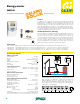
DataLogger
DL2
Function
Product range
Code 257201A DL2 data logger connects to VBus data terminals on iSolar controllers
Technical specifications
CALEFFI
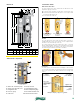
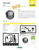
Dimensions
A
1
3/4”
B
5
1/8”
C
4 7/16”
Ø
1/4” mount
Code
257201A
Weight (lb)
3.0
A
B
C
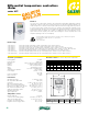
Router
Connection
Connect the datalogger (pos.1) to other modules in the following order:
1. Connect the VBus data wire (pos.3) to the iSolar controller (pos.4).
Extend, if necessary with twisted pair wire up to 150 feet.
2. Plug power adapter (pos.2) into the AC outlet.
3. Connect the datalogger to the network router (pos. 7) by means of
the network cable (enclosed, pos.6).
4. Connect PC (pos. 8) to the router (pos. 7) by a network cable
Integrated Web interface
The DL2 data logger enables the acquisition and storage of large amounts of
data (such as energy metering and recorded values of the solar system) over a
long period of time when connected to an iSolar controller. The DL2 is compat-
ible with all iSolar controllers with VBus data connection terminals and is
connected to the VBus with two conductor wire (bell wire) at least 20 AWG up to
a distance of 150 feet.
The DL2, when connected to a network through the integrated ethernet socket,
can be configured and viewed with any standard internet browser via its
integrated web interface. A configuring IP address and password protection
allows for access from any PC with an internet connection for system monitoring
of energy metering or for reviewing system performance, without additional
software. Download data through the web interface or an SD memory card for
further data processing in spreadsheet programs
Housing: PC-ABS Thermoplastic
Protection type: indoor
Ambient temperature: 32 ... 100º F (0 ... 40º C)
Mounting: wall
Display: bar LED
Input voltage: 5V DC ± 5 %
Power voltage adapter: 100 ... 240 V~
Rated current: 350 mA
Ethernet connection: integrated socket
Data access integrated SD slot
Memory: 180 MB internal memory
CALEFFI
Flexible stainless steel insulated piping
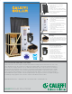
SolarFlex
NA3500
Function
SolarFlex is a system solution with pre-insulated flow and return
pipes for solar hot water heating systems used to connect the solar
collector with the storage tank in an easy, quick and professional
way. It optimizes thermal efficiency of the entire system. The pre-
insulation solution of two flexible stainless steel pipes inside two
EPDM closed cell insulation and the integrated sensor cable, saves
time and reduces cost of installation. SolarFlex is packaged in a 50-
foot continuous coil with a complete range of accessories to ensure
a smoothand secure installation.
General
• Easy to install, enabling pipes to be run without using a torch
in confined spaces or on the roof.
• Ensures a leak-free installation.
• Easy to separate, without damaging the tubes.
• External copolymer foil protects against UV radiation
and mechanical strain.
• Identification mark for flow and return.
• Meets highest requirements for modern solar heating systems.
• Pre-insulated feed and return pipes can be joined easily
without special tools.
Technical specifications
Materials:
- pipe: two corrugated stainless steel 316L
- insulation: two closed cell elastomer UV resistance EPDM
- outer cover: UV resistant polyolefin copolymer foil
Insulation thickness: 5/8 inch (16mm)
Thermal conductivity: 0.215 BTU-in/hr-ft
2
-°F (0.031 W/mK)
Thermal resistance: R-4.2
Max. working pressure: 150 psi (10 bar)
Max. fluid temperature: 350ºF (175ºC)
Min. surface temperature: -60ºF (-50ºC)
Length per coil: 50 feet (15m)
Fluid capacity per foot: 1/2" - 0.0219 gallons (0.08 liters)
3/4" - 0.0346 gallons (0.13 liters)
1" - 0.0509 gallons (0.19 liters)
Min. bending radius: 5 inch (130mm)
Pessure loss:
Approx. 25% more than in a comparable smooth pipe
Flammability: Class VO
Flame spread/smoke density 25/50
Agency approvals: ASTM D 635
ASTM C 177
C
AB C D
1" 1 - 1/4 " 4 -
7/16
"
2-
1/2
"
Code
1/ 2" 11/16 " 4 " 2 "
NA3520 - 15
NA3560 - 15
Weight (lb/f)
3/4" 15/16 " 4 -
3/8
"
2-
1/8
"
NA3540 -15
0.5
0.4
0.7
D
A
B
Product range
NA3520-15 1/2" SolarFlex pipe 50' coil including (2) double nipples, (4) union nuts, 4 segment rings and 4 washers
NA3540-15 3/4" SolarFlex pipe 50' coil including (2) double nipples, (4) union nuts, 4 segment rings and 4 washers
NA3540- B 3/4" SolarFlex pipe bulk cut to length up to 164 foot. Without connection fittings.
NA3560-15 1" SolarFlex pipe 50' coil including (2) double nipples, (4) union nuts, 4 segment rings and 4 washers
Dimensions