
Solar Thermal Information


6
3. SPACE HEATING OPTIONS:
Not every hydronic space heating distribution system is
suitable for use with a solar combisystem. Distribution
systems that operate at low water temperatures are greatly
preferred because they allow for higher solar energy yields.
Space heating distribution systems that provide design
heating load output using supply water temperatures
no higher than 120ºF will allow the solar subsystem to
deliver relatively good performance.
Distribution systems that supply each heat emitter using
parallel piping branches rather than series configurations
are also preferred because they provide the same supply
water temperature to each heat emitter.
Examples of space heating systems that allow the solar
subsystem to provide good performance include:
• Heated floor slabs with low-resistance coverings
• Heated thin-slabs over framed floors with low-resistance
coverings
• Generously sized panel radiator systems with parallel
piping
• Forced-air systems with generously sized water-to-air
heat exchangers and carefully placed diffusers that do
not create drafts
Each of these will be discussed in more detail.
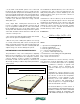
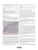
HEATED FLOOR SLABS:
Heated floor slabs with relatively close tube spacing and
low finish floor resistances are generally well suited for
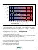
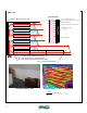
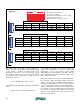
use with solar combisystems. The graph in figure 3-1
shows upward heat output from a heated slab based on
tube spacing of 6 inches and 12 inches, and for finish
floor resistances ranging from 0 to 2.0 (ºF•hr•ft2/Btu).
The steeper the line, the better-suited the distribution
system is for use in a solar combisystem.
For example, achieving an upward heat output of 20
Btu/hr/ft
2
from a slab with no covering (e.g., Rff = 0) and
6-inch tube spacing requires the “driving ∆T” (e.g., the
difference between average water temperature in tubing
and room air temperature) to be 17.5ºF. Thus, in a room
maintained at 70ºF, the average water temperature in the
circuit needs to be 87.5ºF. The supply water temperature
to the circuit would likely be in the range of 95–98ºF.
This is a relatively low supply water temperature, and
should allow the collectors to operate at reasonably good
efficiency, especially if flat plate collectors are used.
For comparison, consider supplying the same 20 Btu/hr/ft
2
load using a heated floor slab with 12-inch tube spacing and
a finish floor resistance of 1.0ºF•hr•ft
2
/Btu. The driving ∆T
must now be 42.5ºF. The average circuit water temperature
required to maintain a room temperature of 70ºF would be
70 + 42.5 = 112.5ºF, and the supply temperature likely in the
range of 120–123ºF. This higher temperature would reduce
the efficiency of the solar collectors, and decreases the total
energy collected by the system during the heating season.
Again, the net effect of such a change on a seasonal basis
would have to be assessed through computer simulation of
a given system.
0
20
40
60
0 10 20 30 40 50 60 70 80 90 100
upward heat flux
(Btu/hr/ft2)
Driving ∆T (Tw-Tr) (ºF)
Average water temp. - room air temp
6-inch tube spacing
12-inch tube spacing
Rff=0 Rff=0.5
Rff=1.0
Rff=1.5
Rff=2.0
Upward heat output
vs.
Driving ∆T
for 4" concrete slab
Rff = resistance of finish flooring (ºF/hr/ft^2/Btu)
figure 3-1
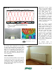
figure 3-2