
Solar Thermal Information

57
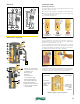
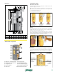
Construction details
Shut-off and check valve
The shut-off and check valves are built into the ball valves of the
temperature gauge connectors.
A.
In normal system operation, the ball valves must be fully open.
B.
To allow the fluid to flow in both directions, it is necessary to rotate
the respective ball valve to 45°.
C.
To close ball valve, rotate 90º.
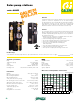
Flow meter
The Flow meter is for measurement and display of the flow rate of 1/2
to 5 gpm (1-20 l/min). For accurate function of the measuring device
the system must be flushed and free from foreign substances.
Air vent
The solar pump unit version with flow and return connection is
equipped with an air vent on the flow line. The air, separated from
the fluid, is collected at the top of the vent.
The collected air must be released from time to time — every day
after the initial installation; however, it can eventually be done weekly
or monthly, depending on the quantity of the air. The collected air is
released using the manual air vent with a screwdriver.
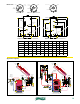
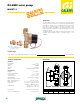
Dimensions
1/2 – 3.5 gpm
(1-13 l/min)
4 – 5 gpm
(15-20 l/min)
nim/ lag 3 .xorppa = yalpsid elpm axE
Left scale:
Upper edge
of the
propeller
Right scale:
Lower edge
of the
propeller
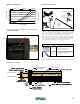
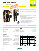
1 Wilo-Solar circulation pump
2 Safety relief valve 253 series
3 Filling/drain valve
4 Pressure gauge
5 Flow meter
6 Air trap and vent
7 Flow temperature gauge
8 Return temperature gauge
9 Pre-formed insulation shell
10 Shut-off and check valve
11 Expansion Tank connection kit
12 3/4" cap (used if no expansion
tank is installed)
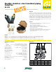
Characteristic components
° 09 ° 54 °0
Check valve in operation,
flow-through only in
flow direction
Check valve not operating,
flow-through in
both directions
Ball valve closed,
no flow-through
A
C
B