
Solar Thermal Information


5
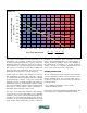
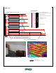
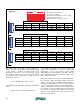
For a given solar radiation intensity and outdoor air
temperature, any operating condition that increases
the fluid temperature entering the collector causes the
inlet fluid parameter to increase. This causes a drop in
thermal efficiency for both the flat plate and evacuated
tube collectors. Conversely, any operating condition that
lowers the inlet fluid temperature also lowers the inlet
fluid parameter and increases collector efficiency.
Systems that can operate with relatively low collector
inlet temperatures generally allow flat plate collectors
to reach thermal efficiencies higher than those attained
by evacuated tube collectors. Conversely, systems that
require the collector to operate at higher temperatures are
usually better suited to evacuated tube collectors. Design
tools such as simulation software can be used to determine
which type of collector allows a given combisystem to
harvest the greatest amount of solar energy.
The value of the inlet fluid parameter often changes
from moment to moment depending on the operating
conditions of the system and the prevailing weather. For
example, if a cloud temporarily shadows the collectors
from direct sun, the value of the inlet fluid parameter could
easily double, which temporarily decreases efficiency.
Designers are cautioned about assuming any given
value of the inlet fluid parameter as “representative” of
average operating conditions. Instead, the variability of
this parameter is accounted for in system simulation
software. The latter is essential in determining the net
effect of any collector in a solar combisystem.
FREEZE PROTECTION:
All solar combisystems require a means of protecting the
collectors and piping outside of the heated space from
freezing. Although there are several possible ways to
do this, two methods of freeze protection dominate the
market worldwide:
• Use of antifreeze fluid in the collector circuit
• Gravity drainback systems
Each of these systems has advantages and limitations, and
several options for each approach will be described.
0
0.1
0.2
0.3
0.4
0.5
0.6
0.7
0.8
0.9
1
0 0.1 0.2 0.3 0.4 0.5 0.6 0.7 0.8 0.9 1 1.1
collector thermal efficiency
(decimal %)
Inlet fluid parameter
T
i
− T
a
I
º F ⋅ ft
2
⋅ hr
Btu
glazed flat plate collector
evacuated tube collector
figure 2-2