
Solar Thermal Information


47
Next determine which side of the heat exchanger has
the minimum fluid capacitance rate (e.g., calculate the
product (8.01 x D x c x f) for each flow stream and
determine which is smaller).
For the hot side of the heat exchanger:
For the cool side of the heat exchanger:
The fluid capacitance rate on the hot side of the heat
exchanger is the smallest.
Determine the maximum possible heat transfer across the
heat exchanger. This corresponds to a thermodynamic
limit in which the outlet temperature of the fluid with
the lower fluid capacitance rate approaches the inlet
temperature of the other fluid stream. It is determined
by multiplying the minimum fluid capacitance rate by the
difference in temperature between the entering hot fluid
and the entering cool fluid. This difference is often called
the “approach” temperature difference.
Finally, determine the effectiveness of the heat exchanger
under these conditions.
COLLECTOR HEAT EXCHANGER
PERFORMANCE PENALTY:
The decrease in solar energy collected as a result of
having a heat exchanger between the collector loop
fluid and the storage tank can be estimated using the
following formula.
Where:
CF = correction factor (derating multiplier)
F
R
U
L
= slope of collector efficiency line (Btu/hr/ft
2
/ºF)
A
CA
= area of collector array (ft
2
)
D = density of collector loop fluid (lb/ft
3
)
c = specific heat of collector loop fluid (Btu/lb/ºF)
f
ca
= fluid flow rate through collector array (gpm)
e = effectiveness of collector/storage heat exchanger.
The correction factor is a derating multiplier. For example,
if the correction factor were 0.95, the collector array and
heat exchanger used as a system, would gather 95%
of the amount of solar energy compared to the same
collector array without the heat exchanger. This could
also be viewed as a 5% performance penalty due to the
presence of the heat exchanger.
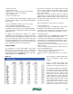
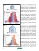
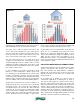
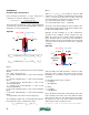
Figure B-3 shows how the correction factor varies as a
function of the heat exchanger’s effectiveness. This graph
is for a small combisystem using four 4-foot by 8-foot flat
plate collectors, a 50% solution of propylene glycol as the
collector fluid and a flow rate of 1 gallon per minute per
collector. The collector’s efficiency line has a slope (F
R
U
L
)
of 0.865 Btu/hr/ft
2
/ºF.
The graph shows that heat exchangers with low
effectiveness numbers (less than 0.55) create significant
performance penalties (over 5% reduction in energy gain). It
is suggested that all collector-to-storage heat exchangers
used in solar combisystems have effectiveness ratings of
0.55 or higher, and thus impose losses of not more than
5% on solar energy collection.
0.6
0.65
0.7
0.75
0.8
0.85
0.9
0.95
1
0 0.1 0.2 0.3 0.4 0.5 0.6 0.7 0.8 0.9 1
collector performanc multiplier
heat exchanger eectiveness
For the 40% propylene glycol solution:
D = 64.0 lb/ft
3
c = 0.91 Btu/lb/ºF
For water:
D = 61.8 lb/ft
3
c = 1.00 Btu/lb/ºF
Next, calculate the actual rate of heat transfer across the heat exchanger. This
can be done using data from either flow stream. In this case, the data from the
flow stream through the hot side of the heat exchanger (using the 40%
propylene glycol solution) is used:
Q
actual
= (8.01× D
h
× c
h
) × f
h
× Th
in
− Th
out
( )
= (8.01× 64.0 × 0.91) × 4 × 130 − 120
( )
= 18, 660 Btu / hr
Next determine which side of the heat exchanger has the
minimum
fluid
capacitance rate (e.g., calculate the product (8.01 x D x c x f) for each flow
stream and determine which is smaller).
For the hot side of the heat exchanger:
(8.01× D × c × f )
40%PG
= (8.01× 64.0 × 0.91× 4) = 1866
Btu
hr•º F
For the cool side of the heat exchanger:
(8.01× D × c × f )
water
= (8.01× 61.8 × 1.00 × 6) = 2970
Btu
hr•º F
The fluid capacitance rate on the hot side of the heat exchanger is the smallest.
Determine the maximum possible heat transfer across the heat exchanger. This
corresponds to a thermodynamic limit in which the outlet temperature of the
fluid with the lower fluid capacitance rate approaches the inlet temperature of
the other fluid stream. It is determined by multiplying the minimum fluid
capacitance rate by the difference in temperature between the entering hot
fluid and the entering cool fluid. This difference is often called the “approach”
temperature difference.
Q
max
= 8.01× D × c × f
[ ]
min
× Th
in
− Tc
in
( )
= [8.01× 64.0 × 0.91× 4] × 130 − 110
( )
= 37, 320Btu / hr
For the 40% propylene glycol solution:
D = 64.0 lb/ft
3
c = 0.91 Btu/lb/ºF
For water:
D = 61.8 lb/ft
3
c = 1.00 Btu/lb/ºF
Next, calculate the actual rate of heat transfer across the heat exchanger. This
can be done using data from either flow stream. In this case, the data from the
flow stream through the hot side of the heat exchanger (using the 40%
propylene glycol solution) is used:
Q
actual
= (8.01× D
h
× c
h
) × f
h
× Th
in
− Th
out
( )
= (8.01× 64.0 × 0.91) × 4 × 130 −120
( )
= 18,660Btu / hr
Next determine which side of the heat exchanger has the
minimum
fluid
capacitance rate (e.g., calculate the product (8.01 x D x c x f) for each flow
stream and determine which is smaller).
For the hot side of the heat exchanger:
(8.01× D × c × f )
40%PG
= (8.01× 64.0 × 0.91× 4) = 1866
Btu
hr•º F
For the cool side of the heat exchanger:
(8.01× D × c × f )
water
= (8.01× 61.8 ×1.00 × 6) = 2970
Btu
hr•º F
The fluid capacitance rate on the hot side of the heat exchanger is the smallest.
Determine the maximum possible heat transfer across the heat exchanger. This
corresponds to a thermodynamic limit in which the outlet temperature of the
fluid with the lower fluid capacitance rate approaches the inlet temperature of
the other fluid stream. It is determined by multiplying the minimum fluid
capacitance rate by the difference in temperature between the entering hot
fluid and the entering cool fluid. This difference is often called the “approach”
temperature difference.
Q
max
= 8.01 × D × c × f
[ ]
min
× Th
in
− Tc
in
( )
= [8.01 × 64.0 × 0.91 × 4] × 130 −110
( )
= 37, 320Btu / hr
Finally, determine the effectiveness of the heat exchanger under these
conditions.
e =
Q
actual
Q
max
=
18,660
37, 320
= 0.50
Collector Heat Exchanger Performance Penalty:
The decrease in solar energy collected as a result of having a heat exchanger
between the collector loop fluid and the storage tank can be estimated using
the following formula.
CF =
1
1+
F
R
U
L
( )
× A
ca
8.01× D × c × f
ca
×
1
ε
−1
Where:
CF = correction factor (derating multiplier)
F
R
U
L
= slope of collector efficiency line (Btu/hr/ft
2
/ºF)
A
CA
= area of collector array (ft
2
)
D = density of collector loop fluid (lb/ft
3
)
c = specific heat of collector loop fluid (Btu/lb/ºF)
f
ca
= fluid flow rate through collector array (gpm)
e = effectiveness of collector/storage heat exchanger.
The correction factor is a derating multiplier. For example, if the correction
factor were 0.95, the collector array and heat exchanger used as a system,
would gather 95% of the amount of solar energy compared to the same
collector array without the heat exchanger. This could also be viewed as a 5%
performance penalty due to the presence of the heat exchanger.
Figure B-3 shows how the correction factor varies as a function of the heat
exchanger’s effectiveness. This graph is for a small combisystem using four 4-
foot by 8-foot flat plate collectors, a 50% solution of propylene glycol as the
collector fluid and a flow rate of 1 gallon per minute per collector. The
collector’s efficiency line has a slope (F
R
U
L
) of 0.865 Btu/hr/ft
2
/ºF.
[insert figure B-3 ]