
Solar Thermal Information


46
APPENDIX B:
Heat Exchanger Performance:
Heat exchanger performance is often expressed as
“effectiveness,” which is defined as follows:
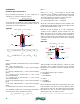
The actual rate of heat transfer can be determined based
on the flow rate, specific heat and temperature change of
either fluid, as shown in figure B-1.
Where:
Q
actual
= actual rate of heat transfer across heat exchanger
(Btu/hr)
8.01 = unit conversion factor
D
h
= density of fluid through hot side of heat exchanger
(lb/ft
3
)
D
c
= density of fluid through cool side of heat exchanger
(lb/ft
3
)
c
h
= specific heat of fluid through hot side of heat
exchanger (Btu/lb/ºF)
c
h
= specific heat of fluid through cool side of heat
exchanger (Btu/lb/ºF)
f
h
= flow rate of fluid through hot side of heat exchanger
(gpm)
f
c
= flow rate of fluid through cool side of heat exchanger
(gpm)
T = temperatures at locations shown in figure (ºF)
The maximum possible rate of heat transfer through the
heat exchanger can be calculated as follows:
Where:
(8.01 x D x c x f)
min
= the smaller of the two fluid
capacitance rates. Found by calculating the product (8.01
x D x c x f) for both the hot and cool side of the heat
exchanger and then selecting the smaller of the two.
Th
in
= inlet temperature of the hot fluid (ºF)
Tc
in
= inlet temperature of the cool fluid (ºF)
As the size of the heat exchanger increases relative to the
required rate of heat transfer, its effectiveness approaches
the theoretical limiting value of 1.0.
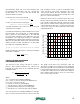
Example: A heat exchanger in a solar combisystem
operates at the conditions shown in figure B-2. The
fluid in the collector loop is a 40% solution of propylene
glycol. The fluid on the cool side of the heat exchanger is
water. Determine the rate of heat transfer across the heat
exchanger and its effectiveness under these operating
conditions.
Start by finding the fluid properties of both the 40%
propylene glycol solution and water at the average
temperature of each fluid as it passes through the heat
exchanger.
For the 40% propylene glycol solution:
D = 64.0 lb/ft
3
c = 0.91 Btu/lb/ºF
For water:
D = 61.8 lb/ft
3
c = 1.00 Btu/lb/ºF
Next, calculate the actual rate of heat transfer across the
heat exchanger. This can be done using data from either
flow stream. In this case, the data from the flow stream
through the hot side of the heat exchanger (using the
40% propylene glycol solution) is used:
Th
out
Th
in
Tc
in
Tc
out
f
c
f
h
hot side cool side
or
Q
actual
= (8.01× D
c
× c
c
) × f
c
× Tc
out
− Tc
in
( )
Q
actual
= (8.01× D
h
× c
h
) × f
h
× Th
in
− Th
out
( )
hot side cool side
130ºF
4 gpm
120ºF
6 gpm
110ºF
116.3ºF
40%
propylene
glycol
water
APPENDIX B: Heat Exchanger Performance:
Heat exchanger performance is often expressed as “effectiveness,” which is
defined as follows:
e=effectiveness = e =
actual heat transfer rate
maximum possible heat transfer rate
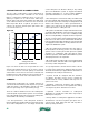
The actual rate of heat transfer can be determined based on the flow rate,
specific heat and temperature change of either fluid, as shown in figure B-1.
[insert figure B-1]
Where:
Q
actual
= actual rate of heat transfer across heat exchanger (Btu/hr)
8.01 = unit conversion factor
D
h
= density of fluid through hot side of heat exchanger (lb/ft
3
)
D
c
= density of fluid through cool side of heat exchanger (lb/ft
3
)
c
h
= specific heat of fluid through hot side of heat exchanger (Btu/lb/ºF)
c
h
= specific heat of fluid through cool side of heat exchanger (Btu/lb/ºF)
f
h
= flow rate of fluid through hot side of heat exchanger (gpm)
f
c
= flow rate of fluid through cool side of heat exchanger (gpm)
T = temperatures at locations shown in figure (ºF)
The maximum possible rate of heat transfer through the heat exchanger can be
calculated as follows:
Q
max
= 8.01 × D × c × f
[ ]
min
× Th
in
− Tc
in
( )
Where:
(8.01 x D x c x f)
min
= the
smaller
of the two fluid capacitance rates. Found by
calculating the product (8.01 x D x c x f) for both the hot and cool side of the
heat exchanger and then selecting the smaller of the two.
Th
in
= inlet temperature of the hot fluid (ºF)
Tc
in
= inlet temperature of the cool fluid (ºF)
As the size of the heat exchanger increases relative to the required rate of heat
transfer, its effectiveness approaches the theoretical limiting value of 1.0.
Example: A heat exchanger in a solar combisystem operates at the conditions
shown in figure B-2. The fluid in the collector loop is a 40% solution of
propylene glycol. The fluid on the cool side of the heat exchanger is water.
Determine the rate of heat transfer across the heat exchanger and its
effectiveness under these operating conditions.
[insert figure B-2]
Start by finding the fluid properties of both the 40% propylene glycol solution
and water at the average temperature of each fluid as it passes through the
heat exchanger.
For the 40% propylene glycol solution:
D = 64.0 lb/ft
3
c = 0.91 Btu/lb/ºF
For water:
D = 61.8 lb/ft
3
c = 1.00 Btu/lb/ºF
Next, calculate the actual rate of heat transfer across the heat exchanger. This
can be done using data from either flow stream. In this case, the data from the
flow stream through the hot side of the heat exchanger (using the 40%
propylene glycol solution) is used:
Q
actual
= (8.01 × D
h
× c
h
) × f
h
× Th
in
− Th
out
( )
= (8.01 × 64.0 × 0.91)× 4 × 130 − 120
( )
= 18,660Btu / hr
Next determine which side of the heat exchanger has the
minimum
fluid
capacitance rate (e.g., calculate the product (8.01 x D x c x f) for each flow
stream and determine which is smaller).
For the hot side of the heat exchanger:
(8.01× D × c × f )
40%PG
= (8.01 × 64.0 × 0.91× 4) = 1866
Btu
hr•º F
For the cool side of the heat exchanger:
(8.01× D × c × f )
water
= (8.01 × 61.8 × 1.00 × 6) = 2970
Btu
hr•º F
The fluid capacitance rate on the hot side of the heat exchanger is the smallest.
Determine the maximum possible heat transfer across the heat exchanger. This
corresponds to a thermodynamic limit in which the outlet temperature of the
fluid with the lower fluid capacitance rate approaches the inlet temperature of
the other fluid stream. It is determined by multiplying the minimum fluid
capacitance rate by the difference in temperature between the entering hot
fluid and the entering cool fluid. This difference is often called the “approach”
temperature difference.
Q
max
= 8.01× D × c × f
[ ]
min
× Th
in
− Tc
in
( )
= [8.01× 64.0 × 0.91× 4] × 130 − 110
( )
= 37, 320Btu / hr
figure B1
figure B2