
Solar Thermal Information

39
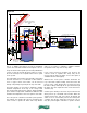
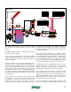
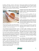
All hydronic subsystems connected to this tank are
pressurized. They include the boiler circuit, domestic
water preheating subsystem and the space heating
distribution system. These subsystems absorb or
dissipate heat to the water in the tank through large,
coiled, copper heat exchangers, such as the one shown
in figure 5-18.
Image courtesy of American Solartechnics
This heat exchanger consists of four parallel “windings”
of copper tube manifolded together at each end. This
configuration produces far less pressure drop than would
a single tube coil of the same total length.
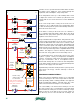
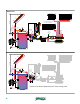
The wood-fired boiler heats the tank through a copper
coil heat exchanger suspended from the top or side of
the tank. This coil and remaining boiler piping constitute
a closed hydronic circuit, and therefore require a
pressure relief valve and expansion tank. Depending on
local codes, the boiler circuit may also require safety
devices such as a low-water cut off or manual reset high
limit. A 3-way thermostatic mixing valve is used to boost
boiler inlet temperature to prevent flue gas condensation
within the boiler. This is essential for minimizing creosote
formation within the boiler and its venting system.
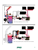
Domestic water is preheated through another suspended
copper coil in the tank. A controller measures the
temperature of the water leaving this coil. If it’s hot
enough to supply the fixtures, the diverter valve
directs it to the anti-scald tempering valve. As in
other combisystems, this valve prevents excessively
hot water from flowing directly to the fixtures. If the
water needs further heating, the diverter valve directs
it through the modulating instantaneous water heater.
After this, it again passes through the anti-scald mixing
valve before going to the fixtures.
Energy for space heating is also extracted from the tank
through a third suspended coil. This coil and the remaining
space heating piping constitute another closed-loop
pressurized subsystem, and thus require a pressure relief
valve and expansion tank.
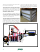
Heat from the collector array is added to the tank through
the drainback subsystem. The tank water passes directly
through the collector circuit. No heat exchangers are
required. The absence of a heat exchanger improves the
efficiency of the collectors.
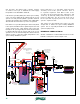
Because this is an open-loop drainback system, the
circulators must be bronze, stainless steel or a high-
temperature polymer to avoid corrosion. A “dual-pumped”
circulator is shown with a time delay relay used to turn off
the upper circulator when the siphon is established in the
collector return piping.
An elbow located just below the operating water level
deflects flow returning from the collectors so it enters the
tank horizontally rather than vertically. This helps preserve
temperature stratification within the tank. A tee is installed
a few inches above the water level to allow air to reenter
the return piping fro drainback.
The water level in the tank is indicated by a sight glass
installed at a suitable height. Water can be added to the
tank through the hose bib valve at the bottom of the
collector loop.
An “inverted-U” piping configuration is used to supply
the collector circulators. This eliminates the need for
piping to penetrate the tank below the water level. This
piping should be kept as short and low to the tank top
as possible. The collector loop circulators should be
mounted as low as possible to maintain some slight
positive pressure at their inlet. The inverted U is primed
by closing an isolation valve on the solar loop circulators
and adding water to the tank at a high flow rate through
the hose bib valve. Once filled, the inverted U should
remain full of water.
The combination of a solar collector array and wood-fired
boiler is synergistic. The boiler will likely be used more
during cold and cloudy winter weather. The solar array
will produce greater outputs in spring and fall, and may
even eliminate the need to operate the wood-fired boiler
for domestic water heating during warm weather.
figure 5-18