
Solar Thermal Information

34
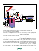
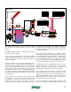
actuator closes to operate the boiler and the boiler circulator.
Hot water is then supplied to space heating through the
HydroLink, and eventually the 3-way mixing valve.
If the temperature at the top of the auxiliary tank is 95ºF
or higher, the outdoor reset controller (C1) allows the solar
storage tank to serve as the heat source for the distribution
system.
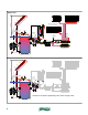
If the solar storage tank is serving as the heat source, it
continues to do so until the tank sensor temperature drops
to 90ºF, at which point the system automatically switches to
the boiler as the heat source.
If the boiler is serving as the heat source, it continues to
do so until the tank temperature climbs above 95ºF (from
additional solar gain). At this point, the solar storage tank
again becomes the heat source.
Keep in mind that these temperatures change based on the
current outdoor temperature. The slope of the reset line, as
well as the differential of the outdoor reset controller, can be
adjusted to suit the type of heat emitters and auxiliary heat
source used in the system. This simple method of switching
between heat sources allows the solar storage to be utilized
to the lowest possible temperature compatible with the heat
emitters. This improves collector efficiency and increases
the total solar energy gathered over the heating season.
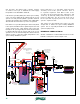
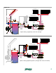
A conventional boiler is shown in this system. As in other
hydronic systems serving low-temperature distribution
systems, such boilers require protection against sustained
flue gas condensation. This is accomplished using a
thermostatic mixing valve to monitor the inlet temperature
to the boiler and boost it when necessary by blending in hot
water from the supply side of the boiler.
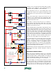
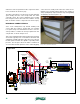
A partial wiring schematic showing how the system operates
(other than solar energy collection function) is shown in
figure 5-12.
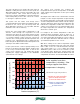
DRAINBACK COMBISYSTEM #3:
Both of the previous drainback designs use a suspended
coil heat exchanger in the solar storage tank for domestic
water preheating. While certainly plausible, this approach
limits potential tank suppliers, especially if the size of the
tank or its internal heat exchanger is “non-standard.”
The serviceability of an internal heat exchanger over the
life of the system is also a consideration. Some tanks allow
the internal heat exchanger to be lifted out through a large
flange at the top of the tank if ever necessary. Others do
not allow any access to the internal heat exchanger. The
24 VAC
L1 N
R1
R
C
3-way
mixing
valve
controller
room
thermostat
M
24 VAC 3-way
diverter valve
w/ end switch
R C
outdoor
reset
controller
(C1)
Boiler circulator powered
through C1, C2 terminal on
boiler limit controller
sensors
P1
P2
DHW tank
thermostat
R2
P3
R2
R2
R1
R1
DHW
tank
heat
source
distribution
system
sensors
R2
(T T)
terminals
on boiler limit
controller
transformer
120/24 VAC
figure 5-12