
Solar Thermal Information

33
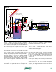
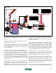
The solar collection process operates the same way as in
drainback combisystem #1. However, in this system, the
differential temperature controller only handles the solar
collection function. Other control devices manage the
heat source selection, distribution of heat and domestic
water heating. Many of these other controls are common
to other types of hydronic systems.
This system uses two tanks: solar storage and a
conventional indirect water heater. No auxiliary heat from
the boiler is ever sent to the solar storage tank. This
allows that tank to remain as cool as possible, and thus
maximizes solar collector efficiency.
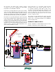
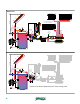
Heat in the solar storage tank is transferred to cold
domestic water through the suspended coil heat
exchanger. This allows the solar storage tank to provide
some domestic water preheating even when it is relatively
cool. However, during or after a period of solar energy
collection, this coil may provide the full temperature rise
required. If not, supplemental heat is supplied by the
boiler through the HydroLink and then through the heat
exchanger of the indirect water heater.
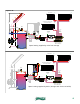
For the system shown, a call for spacing heating comes
from the room thermostat, which supplies 24 VAC power
to the 3-way motorized mixing valve, as well as the
outdoor reset controller (C1). The mixing valve begins
regulating the supply temperature to the distribution
system based on its settings.
The outdoor reset controller (C1) compares the
temperature at the top of the storage tank to a calculated
“ideal” supply water temperature for the space heating
subsystem.
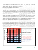
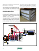
An example of the outdoor reset control function is shown
in figure 5-11. The “target” temperature is represented by
the solid gray sloping line on this graph, and is a function
of outdoor temperature and the current controller settings.
The blue dashed line below the target temperature line
indicates the temperature at which the contacts on the
outdoor reset controller close. The red dashed line above
the target temperature line indicates the temperature
where these contacts open.
For example, if the outdoor temperature is 30ºF, the
calculated target temperature shown in figure 5-1 is
92.5ºF. The lower dashed line indicates that the contacts
close if the temperature at the tank top sensor is 90ºF or
less. The upper dashed line indicates that the contacts
open if that temperature is 95ºF or more.
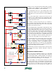
With these settings, if the outdoor temperature equals
30ºF and the temperature at the top of the solar storage
tank is 90ºF or less, the controller determines that the
solar storage tank is too cool to supply the heating
distribution system. It then closes its contacts to power
on the diverter valve, allowing it to change position and
route flow through the boiler. When the diverter valve has
completed its movement, an end switch within the valve’s
Supply water temperature (ºF)
Outdoor temperature (ºF)
70
90
110
130
70 60 50 40 30 20 10 0 -10 -20
contacts on reset controller
close to enable boiler
as heat source
120
100
80
5ºF
differential
(shown)
calculated target temperature
solar tank supplies heat
boiler supplies heat
contacts on reset controller
open to allow solar tank
to serve as heat source
boiler supplies heat when
temperature is climbing. Solar
storage supplies heat when
temperature is dropping
figure 5-11