
Solar Thermal Information

32
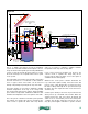
(P1) and (P2). The mixing valve controller operates
on outdoor reset logic to maintain the ideal supply
temperature to the distribution manifold.
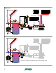
If the boiler is operating during the call for space heating,
some of its heat output will be extracted at the closely
spaced tees that provide hydraulic separation between
circulators (P1) and (P2). The remainder of its output will be
absorbed into the water at the top of the storage tank.
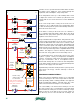
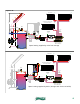
If the boiler is not operating during the call for heat (which
is the expected situation after a significant period of solar
energy collection), the 3-way diverter valve routes flow
through its “B” port, bypassing the boiler. Heated water
is supplied directly from the storage tank to the closely
spaced tees. The motorized mixing valve draws in the hot
water it needs to control the supply temperature to the
space heating distribution system.
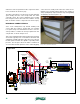
Notice that there is no automatic make-up water
assembly used on this system. Likewise, there is
no separate expansion tank. Minor water losses
over time can be monitored at the sight glass, and
“made up” by manually adding water through a low-
point hose bib valve. The air reservoir at the top of
the storage tank, if properly sized, can serve as the
system’s expansion tank.
This system uses the thermal mass at the top of the
storage tank to “buffer” the space heating distribution
system. This is especially desirable if the distribution
system is highly zoned.
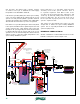
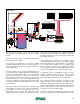
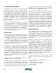
DRAINBACK COMBISYSTEM #2:
Another combination of subassemblies has been used to
build the combisystem shown in figure 5-10.
DHW coil
PRV
All solar circuit piping
sloped minimum 1/4"
per ft.
sight
glass
static
water
level
lift head
cold
storage / drainback tank
air space
air return
tube
(P3b)
(P3a)
time
delay
relay
differential
temperature
controller
3-way
motorized
mixing valve
(reset control)
outdoor
temperature
sensor
stor.
diverter
valve
HyroLink
room
thermostat
outdoor
temperature
sensor
outdoor
reset
controller (C1)
conventional boiler
(requires protection
from flue gas
condensation)
other
heating
load
zone
relays
heat source
circulator (P1)
distribution
circulator (P2)
anti-condensation
mixing valve
boiler
circulator (P3)
AB
A
B
(P3)
anti-scald
tempering
valve
hot
figure 5-10