
Solar Thermal Information

31
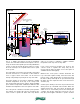
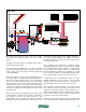
This is a slightly pressurized closed-loop drainback
system. The same water that flows through the collector
array can also flow through the space heating distribution
system, as well as through the boiler when necessary.
No heat exchangers are required between these parts
of the system.
The suspended coil near the top of the tank is for heating
domestic hot water. It is constructed of either stainless
steel or copper, and in some tanks, can be removed
through a large flanged opening at the top of the tank.
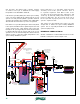
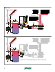
The boiler operates as necessary to maintain a suitable
minimum temperature at the top of the storage tank.
This ensures that domestic hot water is always available
upon demand. Temperature stratification within the tank
minimizes heat migration to the lower portion of the tank.
The solar system controller used in this system provides
two outputs. One operates the collector circulator(s). The
other is used to operate the boiler and 3-way diverter
valve as necessary to maintain a suitable minimum
temperature at the top of the storage tank.
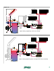
If two series-connected circulators are used for the
collector circuit, a separate time delay relay can be
used to turn the upper circulator off once the siphon is
established in the return piping.
Whenever the solar system controller determines the
top of the tank requires heating, it fires the boiler and
powers on the 3-way diverter valve so flow passes from
the valve’s “AB” port through its “A” port, and on through
the boiler. The same signal also turns on the heat source
circulator (P1).
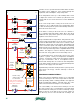
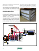
A call for space heating comes from any zone thermostat,
which powers up a manifold valve actuator. When the
actuator reaches the end of its travel, an internal end
switch closes to send 24 VAC power to the mixing valve
controller. This 24 VAC signal also powers the coil of a
relay (R1), which applies 120 VAC to operate circulator
DHW coil
PRV
All solar circuit piping
sloped minimum 1/4"
per ft.
sight
glass
static
water
level
lift head
cold water
check
valve
AB
3-way
diverter
valve
A B
(P1)
closely spaced tees
outdoor
temperature
sensor
(P2)
pressure-
regulated
circulator
space-heating circuits
(highly zoned)
heat source
circulator
relay
manifold valve actuator
thermostat
end switch leads
3-way
motorized
mixing
valve
end switch leads from actuators
relay
storage / drainback tank
air space
air return
tube
air pressure
control valve
(P3b)
(P3a)
time
delay
relay
differential
temperature
controller
hot water
recirculation
figure 5-9