
Solar Thermal Information

30
In some systems, particularly open-
loop systems using translucent
polymer storage tanks, it may be
possible to see the water level as a
shadow line on the tank wall or by
looking into the tank through a small
opening at the top. A “dip stick”
is another possibility for checking
water level in such systems.
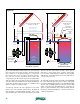
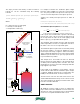
In a closed-loop pressurized sys-
tem, a “sight glass” is the common
solution for checking water level
(see figure 5-8). The sight glass
can be mounted within the upgoing
collector supply piping, directly to
the storage tank, or to two other
piping locations on the same side
of the collector circuit — one above
and one below the static water
level. In all cases, the water in the
system seeks a single level when
the collector circulators are off. It is
advisable to place the sight glass
where it can be easily accessed.
Some sight glasses are made of
temperature resistant glass, others
may use temperature resistant translucent polymers. It is
even possible to use a piece of translucent PEX tubing
as a sight “glass” provided it is operated within its rated
temperature/pressure range.
It is suggested that the sight glass tube be a minimum of
12 inches long and centered on the desired static water
level in the tank. Longer sight glasses will obviously
allow more variations in water level to be detected. Sight
glasses should also be serviceable. The transparent or
translucent tube itself may accumulate a film over time
and require removal for cleaning or replacement. Install
isolating ball valves to ensure such service is possible
without need of draining the storage tank.
TANK PIPING CONNECTIONS:
There are several ways to detail the piping at the top and
bottom of a drainback tank. As previously mentioned, most
open-loop drainback systems bring all piping connections
through the top or high side wall of the tank, and above the
static water level. This reduces the possibility of leakage as
gaskets at such connecting points age.
In open-loop systems, an inverted U-tube is used to draw
water from the lower portion of the tank to the collector
circulator(s) (see figure 5-4). The top of this U-tube should
be kept as close to the top of the tank as possible. It
should also use generously sized piping to minimize
frictional head loss. The inverted U-tube is “primed”
with water by closing an isolation flange on the collector
circulator and adding water at a high flow rate through
the hose bib valve below the collector circulator. The
objective is to displace air within the upper portion of
the U-tube. Once this is accomplished, the water will
remain in place when the circulators are off. A valve
can be added to the top of the U-tube to minimize
the amount of air needing to be displaced at priming;
however, be sure this valve is tightly sealed at all other
times to maintain the priming water in place. Do not
place a float-type air vent or vacuum breaker at the top
of the inverted U-tube. Since this portion of the piping
is under negative pressure relative to the atmosphere,
either of these devices will allow air into the system.
There are also numerous variations in how the return piping
from the collector array attaches to the tank. It is crucial
that all such connections allow air to flow backward into
the return piping at the onset of the drainback process.
It is also preferable that the water enters the storage
tank horizontally. This minimizes disruption of the vertical
temperature stratification within the tank.
If the return piping enters the drainback tank above the
operating water level, there will be a slight “water fall”
sound created by the water falling from the end of the
pipe to the water level in the tank. Although a matter
of opinion, a drop of perhaps a few inches within a
well insulated tank, located in a mechanical room
away from primary living space, should not create
objectionable sounds.
If the return pipe enters the tank below the operating
water level, a separate air equalization tube must be used
as shown in some schematics within this section. Some
of the flow returning from the collectors may pass into
this tube as the system operates. However, momentum
will carry most of the flow past the tee where the air
equalization tube connects to the collector return piping,
and thus most of the water will enter below the water
level in the tank.
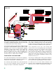
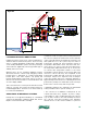
DRAINBACK COMBISYSTEM #1:
The first complete drainback combisystem we’ll discuss
is shown in figure 5-9. This system may look familiar to
those who have read section 4. It uses the same boiler,
near-boiler piping and distribution system concept
as shown with antifreeze-based system #2. The only
difference is that a drainback solar subsystem is now
in place.
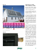
Image courtesy of Hot Water
Products, Inc.
figure 5-8