
Solar Thermal Information

29
The vapor pressure and density of water needed for
formula 5-1 can be calculated using the following
formulas:
Where:
P
v
= vapor pressure of water (psia)
D = density of water (lb/ft
3
)
T = temperature of water (ºF)
For example: Determine the maximum siphon height
based for water at 200ºF in a system at sea level (where
Pa = 14.7 psia), and where the pressure at the top of the
collector circuit is 10 psi above atmospheric pressure.
Solution: The density and vapor pressure of water at
200ºF is:
The maximum siphon height is then calculated:
If the system were installed with a greater vertical drop
from the top of the collector circuit to the water level in
the storage tank, the water in the return piping would
flash to vapor (e.g., boil) and break the siphon.
The maximum siphon height decreases with increasing
water temperature, because as temperature increases,
the water comes closer to its vapor flash point.
The maximum siphon height can be increased by raising
the pressure within a closed-loop drainback system.
Increased pressure helps “suppress” water from boiling.
This is a significant advantage of a closed-loop pressurized
drainback system relative to an open-loop system where
no pressurization is possible.
This analysis does not include the effect of frictional
pressure drop in the return piping, or the potential effect
of adding a flow-restricting device near the end of the
return piping to increases pressure in that pipe and thus
help suppress vapor flash.
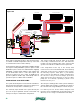
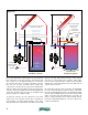
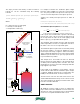
If the height of the building is such that the collector
circuit must be taller than the maximum siphon height,
a separate drainback tank may be located high in the
building to limit the lift head, as shown in figure 5-7.
The lift head is now from the static water level in the
elevated drainback tank to the top of the collector circuit.
The vertical height of the piping circuit below this water
level does not affect lift head.
SIGHT GLASSES:
All drainback systems require a means of verifying the
proper water level in the drainback reservoir. This is true
when the top of the storage tank serves as the drainback
reservoir or if a separate drainback tank is used.
PRV
All exposed piping
sloped minimum
1/4" per ft.
2 circulators
in series
or
1 high head
circulator
storage tank
lift head
air space
for drainback
and expansion
sight
glass
static water
level
insulated
drainback
tank
figure 5-7
rapidly (because there is no flow through it). The controller would detect this,
and increase circulator speed to reestablish the siphon.
In addition to adequate flow velocity in the collector retun piping, siphon
stability depends on a relationship between the water’s temperature, its
corresponding vapor pressure, and the vertical distance between the top of the
collector circuit and the water level in the storage tank.
A conservative estimate for the maximum siphon height that can exist can be
found with formula 5-1:
Formula 5-1
H
max
=
144
D
P
a
+ P
top
− P
v
( )
Where:
H
max
= maximum siphon height
D = density of water at maximum anticipated temperature (lb/ft
3
)
P
a
= atmospheric pressure (psia)
P
top
= extra pressurization (above atmospheric) at the top of the collector
circuit (psi)
P
v
= vapor pressure of water at maximum anticipated temperature (psia)
The vapor pressure and density of water needed for formula 5-1 can be
calculated using the following formulas:
P
v
= 0.771 − 0.0326 × T + 5.75 × 10
−4
( )
× T
2
− 3.9 ×10
−6
( )
× T
3
+ 1.59 × 10
−8
( )
× T
4
D = 62.56 + 3.413 ×10
−4
( )
T − 6.255 × 10
−5
( )
T
2
Where:
P
v
= vapor pressure of water (psia)
D = density of water (lb/ft
3
)
T = temperature of water (ºF)
For example: Determine the maximum siphon height based for water at 200ºF
in a system at sea level (where P
a
= 14.7 psia), and where the pressure at the
top of the collector circuit is 10 psi above atmospheric pressure.
Solution: The density and vapor pressure of water at 200ºF is:
D = 62.56 + 3.413 ×10
−4
( )
200 − 6.255 × 10
−5
( )
200
2
= 60.1lb / ft
3
P
v
= 0.771 − 0.0326 × 200 + 5.75 × 10
−4
( )
× 200
2
− 3.9 × 10
−6
( )
× 200
3
+ 1.59 × 10
−8
( )
× 200
4
= 11.49 psia
The maximum siphon height is then calculated:
H
max
=
144
D
P
a
− P
v
+ P
top
( )
=
144
60.1
14.7 −11.49 +10
( )
= 31.7 ft
If the system were installed with a greater vertical drop from the top of the
collector circuit to the water level in the storage tank, the water in the return
piping would flash to vapor (e.g., boil) and break the siphon.
The maximum siphon height decreases with increasing water temperature,
because as temperature increases, the water comes closer to its vapor flash
point.
The maximum siphon height can be increased by raising the pressure within a
closed-loop drainback system.
Increased pressure helps “suppress” water from
boiling. This is a significant advantage of a closed-loop pressurized drainback
system relative to an open-loop system where no pressurization is possible.
This analysis does not include the effect of frictional pressure drop in the return
piping, or the potential effect of adding a flow-restricting device near the end of
the return piping to increases pressure in that pipe and thus help suppress
vapor flash.
If the height of the building is such that the collector circuit must be taller than
the maximum siphon height, a separate drainback tank may be located high in
the building to limit the lift head, as shown in figure 5-7.
[insert figure 5-7]
For example: Determine the maximum siphon height based for water at 200ºF
in a system at sea level (where P
a
= 14.7 psia), and where the pressure at the
top of the collector circuit is 10 psi above atmospheric pressure.
Solution: The density and vapor pressure of water at 200ºF is:
D = 62.56 + 3.413 ×10
−4
( )
200 − 6.255 × 10
−5
( )
200
2
= 60.1lb / ft
3
P
v
= 0.771 − 0.0326 × 200 + 5.75 ×10
−4
( )
× 200
2
− 3.9 ×10
−6
( )
× 200
3
+ 1.59 ×10
−8
( )
× 200
4
= 11.49 psia
The maximum siphon height is then calculated:
H
max
=
144
D
P
a
− P
v
+ P
top
( )
=
144
60.1
14.7 −11.49 +10
( )
= 31.7 ft
If the system were installed with a greater vertical drop from the top of the
collector circuit to the water level in the storage tank, the water in the return
piping would flash to vapor (e.g., boil) and break the siphon.
The maximum siphon height decreases with increasing water temperature,
because as temperature increases, the water comes closer to its vapor flash
point.
The maximum siphon height can be increased by raising the pressure within a
closed-loop drainback system.
Increased pressure helps “suppress” water from
boiling. This is a significant advantage of a closed-loop pressurized drainback
system relative to an open-loop system where no pressurization is possible.
This analysis does not include the effect of frictional pressure drop in the return
piping, or the potential effect of adding a flow-restricting device near the end of
the return piping to increases pressure in that pipe and thus help suppress
vapor flash.
If the height of the building is such that the collector circuit must be taller than
the maximum siphon height, a separate drainback tank may be located high in
the building to limit the lift head, as shown in figure 5-7.
[insert figure 5-7]