
Solar Thermal Information

28
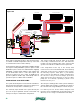
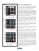
To establish a siphon, the flow rate at operating point
OP4 must produce a corresponding flow velocity within
the return piping of 2 feet per second or higher. The flow
rates necessary for a flow velocity of 2 feet per second in
type M copper tubing are shown in figure 5-6.
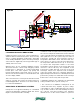
Water at a flow velocity of 2 feet per second or higher
can entrain air bubbles and drag them along. This action
eventually rids the return piping of air, displacing it back
to the top of the storage tank. At that point, a siphon is
established in the return line. Think of the water going down
the return pipe as helping “pull” water up the supply pipe.
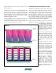
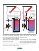
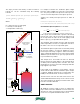
The formation of a siphon causes the system curve to shift
downward, as depicted by the light blue curves t4, t5, t6,
t7, and finally the dark blue curve t8. In a typical residential
drainback system, this sequence may take 30 seconds to
perhaps 3 minutes. Depending on the details at the top
of the storage tank, the system’s pressure and the height
of the collector array, much of the initial “lift head” is now
recovered by the downward “pull” of the siphon.
When the upstream circulator is turned off, the operating
point shifts to a final position marked as OP8. This point
determines the flow rate the collector array operates at
during the remainder of the solar collection cycle. Notice
that the flow rate at the stable operating point OP8 is
higher than the flow rate through the collectors when the
water first passes over the top of the collector circuit with
both circulators operating. For the example given, it is
about 7.2 gallons per minute.
The solid red pump curve in graph 3 is shifted slightly below
the pump curve for the single circulator. It represents the
“net” effect of the lower circulator pumping through the
volute of the upstream circulator, which is now off.
A similar solar collection cycle process occurs in
systems that use a single speed-controlled high-head
circulator. The circulator starts at full speed to quickly
push water up through the collector array and establish
the siphon. After some period of time, the circulator
reduces its speed (based on user programmed settings).
The intersection of the circulator’s reduced speed pump
curve and the system curves after the siphon has
formed determines the stabilized flow rate through the
collector array for the remainder of the cycle.
SIPHON LIMITATIONS:
Once a siphon is established within a drainback system,
it’s important to maintain it until no further solar energy
collection is possible.
Modern controllers, which vary collector
circulator speed in response to the difference
between the collector temperature and
storage tank temperature, have a minimum
speed function intended to maintain the
siphon under reduced speed operation.
If the siphon does break, the collector
temperature would rise rapidly (because
there is no flow through it). The controller
would detect this, and increase circulator
speed to reestablish the siphon.
In addition to adequate flow velocity in
the collector retun piping, siphon stability
depends on a relationship between the
water’s temperature, its corresponding vapor
pressure, and the vertical distance between
the top of the collector circuit and the water
level in the storage tank.
A conservative estimate for the maximum siphon height
that can exist can be made using formula 5-1:
Formula 5-1
Where:
Hmax = maximum siphon height
D = density of water at maximum anticipated temperature
(lb/ft
3
)
P
a
= atmospheric pressure (psia)
P
top
= extra pressurization (above atmospheric) at the top
of the collector circuit (psi)
P
v
= vapor pressure of water at maximum anticipated
temperature (psia)
Tubing
1/2" type M copper 1.6 gpm
3/4" type M copper 3.2 gpm
1" type M copper 5.5 gpm
1.25" type M copper 8.2 gpm
1.5" type M copper 11.4 gpm
2" type M copper 19.8 gpm
2.5" type M copper 30.5 gpm
3" type M copper 43.6 gpm
figure 5-6
Flow rate to establish
2 ft/sec flow velocity
rapidly (because there is no flow through it). The controller would detect this,
and increase circulator speed to reestablish the siphon.
In addition to adequate flow velocity in the collector retun piping, siphon
stability depends on a relationship between the water’s temperature, its
corresponding vapor pressure, and the vertical distance between the top of the
collector circuit and the water level in the storage tank.
A conservative estimate for the maximum siphon height that can exist can be
found with formula 5-1:
Formula 5-1
H
max
=
144
D
P
a
+ P
top
− P
v
( )
Where:
H
max
= maximum siphon height
D = density of water at maximum anticipated temperature (lb/ft
3
)
P
a
= atmospheric pressure (psia)
P
top
= extra pressurization (above atmospheric) at the top of the collector
circuit (psi)
P
v
= vapor pressure of water at maximum anticipated temperature (psia)
The vapor pressure and density of water needed for formula 5-1 can be
calculated using the following formulas:
P
v
= 0.771 − 0.0326 × T + 5.75 ×10
−4
( )
× T
2
− 3.9 ×10
−6
( )
× T
3
+ 1.59 ×10
−8
( )
× T
4
D = 62.56 + 3.413 ×10
−4
( )
T − 6.255 ×10
−5
( )
T
2
Where:
P
v
= vapor pressure of water (psia)
D = density of water (lb/ft
3
)
T = temperature of water (ºF)