
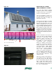
Solar Thermal Information

26
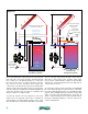
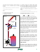
Most of the drainback combisystems to be presented in
this section are closed-loop systems. The water and air
they contain is, for all practical purposes, sealed into
the system. Like other closed-loop hydronic systems,
they can use cast iron circulators and contain steel
components. The dissolved oxygen in the initial water
and air volume will react with any ferrous metal in the
system, forming a very light and essentially insignificant
oxide film. At that point, the water is neutralized and
will not continue to oxidize metals.
Closed-loop systems can also experience very minor
water losses over a period of time due to weepage at
valve packing or circulator flange gaskets. Some of the
dissolved air in the cold water used to fill the system will
also be removed and vented over time. These effects
will cause a minor drop in the system’s static water
level over time. Small amounts of water can be manually
added to the system through the lower hose bib valve to
correct for these losses.
An automatic make-up water assembly should NEVER
be connected to this type of system. Doing so, especially
in systems with high-performance air separating/venting
devices, will eventually replace the air in the system with
water. Over time this will eliminate the necessary air
space for proper drainage and could eventually lead to
freezing of water-filled piping or collectors exposed to
outdoor temperatures.
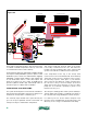
figure 5-4
sight
glass
static
water
level
lift head
tank open
to atmosphere
atmospheric pressure
circulators
must be rated
for "open"
systems
"open loop"
drainback system
Some water will
evaporate from
tank over time
All solar circuit piping sloped
minimum 1/4" per ft.
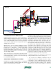
tank
temperature
sensor
(in well)
sight
glass
static
water
level
lift head
air
equilization
tube
air pressure
control valve
(P3b)
(P3a)
"closed loop"
drainback system
pressure gauge
pressure
relief
valve
All solar circuit piping
sloped minimum
1/4" per ft.
pressurized air
tank open
to atmosphere
liner