
Solar Thermal Information

24
which the fluid remains in the collector or flashes to vapor
during stagnation.
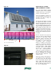
• Because the collectors in a drainback system “dry
stagnate,” there is no need for a heat dump provision.
This is especially relevant to combisystems, which often
have larger collector arrays compared to DHW-only
systems, and thus have increased potential for warm
weather stagnation due to the storage tank reaching a
maximum temperature setting.
• Many drainback systems eliminate the need for an
expansion tank in the system. The air volume that
accommodates drainback water, if properly sized, can
serve as the expansion tank for the system.
DISADVANTAGES OF DRAINBACK SYSTEMS:
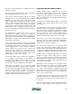
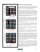
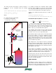
• All piping to and from the collector array, and in some
cases the collectors themselves, must be sloped to
ensure proper drainage. A minimum pitch of 1/4-inch
vertical drop per foot of horizontal run is recommended.
The absorber plates used in some collectors ensure
that they will drain completely. Other collector designs
may require that the entire collector array be sloped to
ensure complete drainage (see figure 5-1). Verify that
any collectors being considered for a drainback system
are approved and warranted for this application.
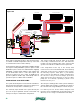
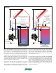
It’s also possible to slope half the collectors in one direction
and half in the other as shown in figure 5-2. In this case,
the supply piping penetrates the
roof at the midpoint between the
two banks of collectors. Return
piping penetrates the roof at
the upper outside corners of
each bank and is joined together
under the roof deck.
There can be no low points in any
piping connecting the collector
array with the storage tank. Any
low points can interfere with
air reentering the collectors,
or create a “trap” that could
eventually freeze and burst the
pipe.
Designers should also ensure
that any “downslope dead ends”
(see figure 5-1) are detailed so
that water will not puddle across
the diameter of the piping. In
general, such dead ends should
be kept as short as possible.
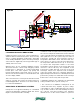
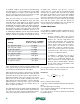
Collectors with an integral sensor
well are preferred for drainback
applications. This detail allows
the sensor to closely track
absorber plate temperature
without relying on convection
of fluid within the collector.
Strapping a sensor to outlet
piping, as is commonly done
with systems using antifreeze
solutions, will delay the control
response. Figure 5-3 shows an
example of an absorber plate
with integrated sensor well.
roof penetration
roof
penetration
"downslope
dead end"
cap
harp style collectors are sloped minimum of 1/4" per ft.
roof
penetration
roof
penetration
vertical serpentine style collectors are mounted level,
but connecting piping is slope minimum of 1/4" per ft.
figure 5-1