
Solar Thermal Information

18
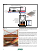
Temperature stratification helps keep this heat at the top of the tank.
The bottom of the tank remains as cool as possible to maximize
collector efficiency. The spring-loaded check valve at the upper outlet
of the tank reduces heat migration through the attached piping. Its
function is especially important in warm weather when no space
heating is required.
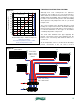
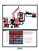
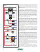
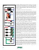
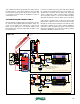
A wiring diagram for this system is shown in figure 4-5.
In this system, the solar controller determines when the top of the tank
requires heating, and if so, turns on the boiler, the heat source circulator
(P1) and powers up the 3-way diverter valve (D1) so flow passes through
the boiler and eventually the upper tank coil. In systems where the solar
controller does not provide this logic, it can be created using standard
hydronic control hardware as described for the previous system.
A call for heating is initiated by any zone thermostat, which powers up
one of the manifold valve actuators. When the associated manifold valve
is fully open, an end switch within the actuator closes. This provides 24
VAC power to operate the 3-way motorized mixing valve (C2), which
then regulates supply temperature to the distribution system based on
outdoor temperature. Relay (R1) is also energized to turn on the heat
source circulator (P1), and the distribution circulator (P2).
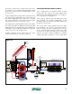
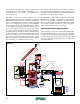
If the boiler is NOT operating, there is no power to the 3-way diverter
valve (D1). Flow passes from the tank’s upper coil into the “AB” port of
the diverter valve, and then out through the valve’s “B” port. It moves
on through the air separator to a pair of closely spaced tees. The
latter provide hydraulic separation between circulators (P1) and (P2).
Hot water passes from the side port of the upper tee to the hot port
of the motorized mixing valve as required to achieve the necessary
supply temperature. The distribution system could supply any of
the lower temperature heat emitters discussed earlier, and it could
be extensively zoned. In the latter case, a variable-speed pressure-
regulated circulator (P2) provides differential pressure control in
response to operation of the zone valves. A normally closed contact
on relay (R1) is now open to prevent line voltage from energizing the
diverter valve (D1).
When the temperature in the upper portion of the storage tank drops
to a lower limit, (based on the system’s ability to supply adequate
domestic hot water), the diverter valve (D1) is powered on by the solar
controller. Flow now passes from this valve’s “AB” port out through its
“A” port and onward through the boiler. When the diverter valve (D1)
reaches the end of its travel, an end switch within the valve’s actuator
closes to fire the boiler.
If the space heating distribution system is also operating while the boiler
is firing, some of the boiler’s heat output is used for space heating. Any
remaining heat output is transferred to the upper portion of the storage
tank by the upper heat exchanger coil. If the space heating distribution
system is not operating, line voltage from the solar controller passes
through the normally closed relay contact (R1) to operate the heat
source circulator (P1).
M
collector
circulator
P3
24 VAC
P1
P2
heat
source
circulator
distribution
system
circulator
transformer
120/24 VAC
R1
3-way
mixing
valve
controller
(C2)
R
C
sensors
R1 (relay coil)
thermostat
M
thermostat
M
thermostat
M
L1 N
120 VAC
sensors
diverter
valve (D1)
(120 VAC
actuator)
solar
controller
R1
(T T)
terminals
on boiler
R1
figure 4-5