
Solar Thermal Information

17
heat source. If the boiler is serving as the heat source,
it continues to do so until the tank temperature climbs
above 95ºF, at which point the auxiliary tank becomes
the heat source.
Keep in mind that these temperatures change based on
the current outdoor temperature. The slope of the reset
line and the differential of the outdoor reset controller
can also be adjusted to suit the type of heat emitters
and auxiliary heat source used in the system.
This simple logic for switching between heat sources allows
the solar storage tank to be utilized to the lowest possible
temperature that can still satisfy the space heating load.
This improves collector efficiency, and increases total solar
energy collection over the heating season.
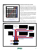
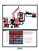
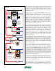
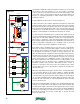
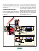
A wiring schematic for this system using the control
method described above is shown in figure 4-3.
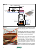
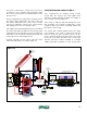
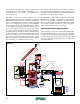
ANTIFREEZE-BASED COMBISYSTEM #2:
Some combisystems are designed around a single
storage tank. The energy in this tank supplies both
domestic hot water and space heating. One example of
such a system is shown in figure 4-4.
Solar energy is added to this tank through the lower
heat exchanger coil. In smaller combisystems, a solar
circulation station (as shown) could likely handle flow
through the collector array.
The storage tank contains potable water. The upper
heat exchanger coil is used to extract heat from this
water for use by the space heating system. It is also
used to add heat produced by the boiler to the water
at the top of the tank. The latter mode ensures that
domestic hot water is always available at a suitable
supply temperature regardless of solar energy input.
air vent
w/ shut off
valve
solar collector array
solar
circulation
station
check
valve
DHW
CW
solar storage tank
(dual coil)
relay
mod/con boiler
make-up water
AB
3-way
diverter
valve (D1)
A B
(P1)
closely spaced tees
outdoor
temperature
sensor
(P2)
pressure-
regulated
circulator
space-heating circuits
(highly zoned)
heat source
circulator
anti-scald
tempering
valve
relay (R1)
manifold valve actuator
thermostat
(1 per zone)
end switch leads
3-way
motorized
mixing
valve
(C2)
end switch leads from actuators
P&T
P3
figure 4-4