
Solar Thermal Information

16
The temperature the auxiliary storage tank reaches depends
on the load and solar availability. During a sustained sunny
period, it is possible for the auxiliary tank to reach a
temperature well above that needed by the space heating
distribution system.
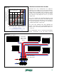
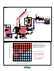
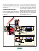
In this system, a call for space heating comes from a
thermostat, which switches 24 VAC power to the 3-way
motorized mixing valve, allowing it to begin operation. 24
VAC power also powers up the coil of relay (R1), which
switches line voltage to operate circulators (P2) and (P3). 24
VAC power also energizes the outdoor reset controller (C3),
which calculates the required supply water temperature for
the space heating based on its settings and the outdoor
temperature. An example of the logic used by the outdoor
reset controller is shown in figure 4-2.
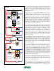
The sloping gray line represents the “target” temperature,
which is the ideal supply water temperature (read from the
vertical axis) for a corresponding outdoor temperature (read
from the horizontal axis). The slope of the gray line can be
adjusted by changing the settings on the controller. The
dashed blue line below the gray line indicates the temperature
at the supply sensor at which the output contacts on the
outdoor reset controller close. The dashed red line above the
gray line indicates the temperature at the supply sensor where
these contacts open.
If, for example, the outdoor temperature is 30ºF, the calculated
target temperature shown in figure 4-2 is 92.5ºF. The lower
dashed line indicates the output contacts close if the temperature
at the supply sensor is 90ºF or less. The upper dashed line
indicates these contacts open if the temperature at the supply
sensor is 95ºF or more.
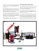
The controller’s supply sensor measures the temperature near
the top of the auxiliary storage tank. Thus, with these settings,
if the outdoor temperature is 30ºF, and the temperature
near the top of the auxiliary storage tank is 90ºF or less, the
controller determines that the auxiliary storage tank is too cool
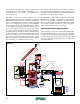
to supply the space heating distribution system. It closes its
output contacts to power on the diverter valve (D2), allowing
it to change position so flow passes through the boiler. When
the diverter valve completes its rotation, an end switch in its
actuator closes to fire the boiler.
When there is a call for space heating, and the temperature at
the top of the auxiliary tank is 95ºF or higher, the outdoor reset
controller allows the auxiliary storage tank to serve as the heat
source for the distribution system.
If the storage tank is serving as the heat source, it continues to
do so until the tank sensor temperature drops to 90ºF, at which
point the system automatically switches to the boiler as the
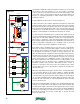
(T T)
terminals
on boiler
M
D2
24 VAC
3-way
mixing
valve
controller
(C2)
room
thermostat
P2
P3
heat
source
circulator
distribution
system
circulator
transformer
120/24 VAC
R1
R
C
sensors
outdoor reset
controller (C3)
R C
sensors
R1 (relay coil)
24 VAC 3-way
diverter valve
w/ end switch
D2
M
collector
circulator
P1
sensors
diverter
valve (D1)
(120 VAC
actuator)
solar
controller
L1 N
120 VAC
figure 4-3