
Solar Thermal Information

14
• Heat exchangers that dissipate surplus heat to high
thermal capacity loads, such as swimming pools, spas
or buried earth loops. The latter is well-suited for
geothermal heat pump systems in climates with relatively
small cooling loads.
• Nocturnal cooling — the antifreeze solution is circulated
between the tank heat exchanger and the collector array
at night to dissipate heat back to the atmosphere. In
some systems, the check valve in the collector loop can
be manually opened to allow nocturnal cooling without
operation of the circulator. Note: Nocturnal cooling can
only be used with flat plate collectors.
Heat dumps (other than nocturnal cooling) are usually
brought online using an electrically operated diverting
valve. In its unpowered state, this valve allows the
antifreeze solution to flow between the collector array
and the normal load — such as a heat exchanger in the
solar storage tank.
When the solar tank reaches a user-specified temperature
limit, the solar system controller powers up the diverting
valve. The heated antifreeze solution returning from the
collector array is then routed to the heat dump. If, during
the heat dump mode, the solar storage tank temperature
drops, the solar system controller discontinues the heat
dump mode and redirects the heated antifreeze to the
normal load.
Power outages are one of the chief causes of collector
stagnation. For a heat dump to be effective during such
times, it must be able to operate in the absence of utility-
supplied power. DC circulators operated from batteries
are one possibility. Passive heat dissipation devices that
operate based on buoyancy-driven flow are another.
Heat dump subsystems should be sized to dissipate
the entire heat gain of the collector array during a warm
and sunny summer day and with no load assumed on
the system. This is based on the premise that two or
more such days could occur in sequence, and that
the first could bring the solar storage tank to its upper
temperature limit. The absence of load during this
scenario is based on the occupants being away from
the building.
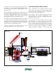
ANTIFREEZE-BASED COMBISYSTEM DESIGNS:
Solar combisystems can be designed many ways
depending on project requirements and constraints.
For example, a narrow doorway might require that a
system needing several hundred gallons of storage is
designed around multiple smaller tanks rather than a
single large tank. A ground-mounted collector array
may not provide the elevation change required for a
drainback system, and thus the only choice would
be an antifreeze-based system. The size of the space
heating load and the type of auxiliary heat used will
certainly influence overall system design. In short,
there is no “universal” design concept for a solar
combisystem that suits all situations.
The remainder of this section discusses several
“templates” for solar combisystems that can work for
many residential or light commercial applications. All
these systems use antifreeze-based closed collector
circuits. Section 5 will present several additional templates
for drainback combisystems.
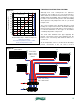
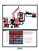
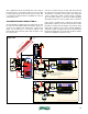
ANTIFREEZE-BASED COMBISYSTEM #1:
The first design presented is a natural extension of a solar
domestic water heating system. It adds an auxiliary storage
tank to accept heat from the collector array whenever
it’s available, and the domestic hot water storage tank
has reached a user-set maximum temperature. A piping
schematic for the system is shown in figure 4-1.
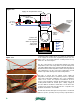
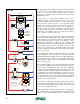
A standard solar circulation station like that used in a
solar DHW system controls flow through the collector
array. Whenever the temperature sensor (S2) on the
domestic water tank is below a user-selectable maximum
setting, flow returning from the collectors is routed to
the left, through the internal heat exchanger in the DHW
storage tank. It then passes into the “B” port of the
3-way diverter valve (D1), out through the “AB” port and
back to the supply side of the solar circulation station.
The diverter valve is not energized in this mode. There is
no flow through the coil in the auxiliary storage tank. A
spring-loaded check valve helps prevent heat migration
into the auxiliary storage tank during this mode.
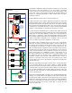
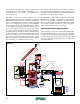
If the solar controller detects that temperature sensor
(S2) has reached the maximum temperature setting,
it applies line voltage to the diverter valve (D1). Hot
antifreeze solution returning from the collectors is now
routed through the coil of the auxiliary storage tank.
As heat is diverted to the auxiliary storage tank, the solar
controller continues to monitor the temperature of the
DHW tank sensor (S2). If its temperature drops a preset
amount, the diverter valve (D1) reverses position to route
the antifreeze solution returning from the collectors
through the coil in the DHW tank. The solar controller
always treats the DHW storage tank as the “priority” load,
directing heat to it whenever its temperature is under a
user-specified maximum value.