Caleffi NorthAmerica, America, Inc. Caleffi North Inc. th 3883 W. Milwaukee 9850 South 54 StreetRd Milwaukee, Wisconsin 53208 Franklin, WI 53132 T: 414.238.2360 414.421.1000 F: T: F:414.421.2878 414.238.2366 Dear Hydronic Professional, Dear Hydronic Professional, Welcome to the 6th edition of idronics, Caleffi’s semi-annual design journal for hydronic Welcome to professionals.
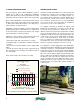
solar thermal combisystems 1. INTRODUCTION Most Americans are increasingly aware of rising energy prices and the environmental implications associated with continued use of conventional fuels. “Sustainable living” is one of the most prevalent topics being discussed in a variety of media. This situation has created growing interest in renewable sources, such as sun, wind and biomass materials. It is also fostering a rapidly expanding market for equipment that harvests this energy.
• In an “ideal” solar thermal system, none of the heat produced by the auxiliary heat source would enter the solar storage tank. This prevents the auxiliary heat source from increasing the temperature of the storage tank above what it would be based solely on solar energy input. Such heating, if allowed to occur, delays the startup of the solar collection cycle, and thus reduces the energy collected during that cycle. Some “single tank” combisystems discussed in this issue do not adhere to this principle.
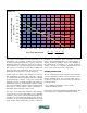
Figure 2-2 1 collector thermal efficiency (decimal %) 0.9 0.8 glazed flat plate collector 0.7 evacuated tube collector 0.6 0.5 0.4 0.3 0.2 0.1 0 0 0.1 0.2 0.3 0.4 0.5 Inlet fluid parameter 0.6 0.7 0.8 0.9 2 Ti − Ta º F ⋅ ft ⋅ hr Btu I 1 1.1 For a given solar radiation intensity and outdoor air temperature, any operating condition that increases the fluid temperature entering the collector causes the inlet fluid parameter to increase.
3. SPACE HEATING OPTIONS: Heated Floor Slabs: Not every hydronic space heating distribution system is suitable for use with a solar combisystem. Distribution systems that operate at low water temperatures are greatly preferred because they allow for higher solar energy yields. Heated floor slabs with relatively close tube spacing and low finish floor resistances are generally well suited for use with solar combisystems.
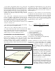
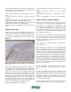
The following guidelines are suggested in applications where a heated floor slab will be used to deliver heat derived from a solar collector array: • Tube spacing within the slab should not exceed 12 inches • Slab should have minimum of R-10 underside insulation • Tubing should be placed at approximately 1/2 the slab depth below the surface, as shown in figure 3-2 • Bare, painted or stained slab surfaces are ideal because the finish floor resistance is essentially zero • Other floor finishes should have a T
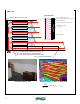
Figure 3-4 crossection wooden nailer (@ end of wall) 7/16" oriented strand board 3/4" foil-faced polyisocyanurate insulation 2.5" drywall screws 6"x24" aluminum heat transfer plates 1/2" PEX-AL-PEX tubing 1/2" drywall fiberglass insulation 1/2" PEX-AL-PEX tubing (8-inch spacing) 6" x 24" aluminum heat transfer plates 3/4" foil-faced polyisocyanurate foam strips 7/16" oriented strand board finished radiant wall thermal image of wall in operation Btu = ( 0.
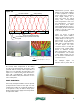
Figure 3-5 top side insulation ceiling framing tube 7/16" oriented strand board aluminum heat transfer plate 3/4" foil-faced polyisocyanurate foam strips 1/2" drywall finished radiant wall thermal image of ceiling in operation Btu = ( 0.71) × (Twater − Troom ) hr • ft 2 the average water temperature in the tubing exceeds room air temperature. Thus, if the ceiling operated with an average water temperature of 110ºF in a room with 70ºF air temperature, each square foot of wall would release about 0.
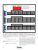
Figure 3-7 length Heat output ratings (Btu/hr) at reference conditions: Average water temperature in panel = 180ºF Room temperature = 68ºF temperature drop across panel = 20ºF height 1 water plate 1 water plate panel thickness 16" long 24" long 36" long 48" long 64" long 72" long 24" high 1870 2817 4222 5630 7509 8447 20" high 1607 2421 3632 4842 6455 7260 16" high 1352 2032 3046 4060 5415 6091 2 water plates 2 water plate panel thickness 16" long 24" long 36" long 48" lo
Forced-Air Distribution Systems: Figure 3-8 1 Although most solar combisystems use hydronics technology, it is possible to use a forced-air system to deliver both the solar-derived heat and any necessary auxiliary heat to the building. This is usually done using a hot water coil mounted in the plenum of the air handling device (furnace, heat pump indoor unit, etc.), as shown in figure 3-10. 1.33 CF = 0.001882 ( ∆T ) 0.8 0.7 reference condition Correction factor (CF) 0.9 0.6 0.5 0.4 0.
Figure 3-10 supply air temperature sensor mixing valve check valve supply air to/from solar storage tank duct coil (in plenum) blower burners off when heated water is supplied from solar subsystem filter return air furnace Figure 3-11 combination with a mixing device to regulate the temperature of the supply air stream. Such regulation prevents very hot water in the solar storage tank from creating a burst of very warm air to the heated space.
in solar combisystems. Most systems using fin-tube baseboard are designed around relatively high water temperatures (180ºF or higher). While it is possible to lower the supply water temperature by adding fin-tube baseboard to the system, lowering it from 180ºF to 120ºF typically requires about 3.5 times as much fin-tube length for the same heat output. Few rooms can physically accommodate this, and few occupants would accept the associated aesthetics.
• Heat exchangers that dissipate surplus heat to high thermal capacity loads, such as swimming pools, spas or buried earth loops. The latter is well-suited for geothermal heat pump systems in climates with relatively small cooling loads. • Nocturnal cooling — the antifreeze solution is circulated between the tank heat exchanger and the collector array at night to dissipate heat back to the atmosphere.
Figure 4-1 air vent w/ shut off valve or ar ra y collector sensor (S1) so la r co lle ct outdoor temperature sensor outdoor temperature sensor room T thermostat (C2) low temperature radiant panel circuits (P3) outdoor reset controller cold water DHW P&T solar circulation station (C3) relay R1 A (P1) (D2) electric element AB B (P2) tank sensor (S2) AB VENT B A (D1) diverter valve DHW storage tank aux. sensor (S3) Aux.
Figure 4-3 L1 N 120 VAC solar controller P1 sensors collector circulator diverter valve (D1) (120 VAC actuator) M P2 heat source circulator R1 P3 distribution system circulator transformer 120/24 VAC 24 VAC room thermostat sensors 3-way mixing valve controller (C2) R C sensors R C D2 M outdoor reset controller (C3) 24 VAC 3-way diverter valve w/ end switch D2 (T T) terminals on boiler R1 (relay coil) 16 The temperature the auxiliary storage tank reaches depends on the load and solar
heat source. If the boiler is serving as the heat source, it continues to do so until the tank temperature climbs above 95ºF, at which point the auxiliary tank becomes the heat source. Keep in mind that these temperatures change based on the current outdoor temperature. The slope of the reset line and the differential of the outdoor reset controller can also be adjusted to suit the type of heat emitters and auxiliary heat source used in the system.
Figure 4-5 L1 N 120 VAC solar controller Temperature stratification helps keep this heat at the top of the tank. The bottom of the tank remains as cool as possible to maximize collector efficiency. The spring-loaded check valve at the upper outlet of the tank reduces heat migration through the attached piping. Its function is especially important in warm weather when no space heating is required. A wiring diagram for this system is shown in figure 4-5.
This configuration allows the thermal mass of the water in the upper portion of the tank to buffer the space heating load, and thus helps prevent boiler short cycling. This is especially beneficial when the distribution system is extensively zoned. Antifreeze-Based Combisystem #3: The functionality of antifreeze-based system #2 can also be achieved using slightly different hardware. Figure 4-6 shows a very similar solar subsystem to that used in figure 4-4.
The speed of circulator (P3) could be varied based on maintaining a fixed supply temperature to the distribution system. It could also be varied based on outdoor reset logic. If circulator (P3) is operated in an on/off manner, a mixing valve is required in the distribution system. Circulator (P3) would turn on whenever the boiler is operating as well as when there is a call for space heating.
The solar collection subsystem is essentially the same as in previous systems. The storage tank contains domestic water and absorbs solar-derived heat through the lower coil. If the domestic water leaving the tank needs a further temperature boost, it is routed through the modulating instantaneous water heater via a 3-way diverter valve, which is operated by a setpoint temperature controller.
Figure 4-8 panel radiator TRV thermostatic radiator valves on each panel radiator TRV TRV ay air vent w/ shut off valve TRV lle ct or ar r TRV so la r co TRV anti-scald tempering valve stainless steel heat exchanger 3-way motorized mixing valve outdoor temperature sensor flow switch manifold distribution system using PEX or PEX-AL-PEX tubing (P2) (P1) integral mod/con burner / heat exchanger pressure-regulated circulator check valve solar circulation station VENT storage tank As th
Figure 4-9 ar ra y air vent w/ shut off valve anti-scald tempering valve CW DHW end switch leads from actuators 3-way motorized mixing valve A AB check valve space-heating circuits (highly zoned) pressureregulated circulator B 3-way diverter valve (P2) closely spaced tees flow switch pool heat exchanger outdoor temperature sensor end switch leads solar circulation station mod/con boiler so la r co lle ct or relay (P1) heat source circulator spring loaded check valve thermostat r
which the fluid remains in the collector or flashes to vapor during stagnation. • Because the collectors in a drainback system “dry stagnate,” there is no need for a heat dump provision. This is especially relevant to combisystems, which often have larger collector arrays compared to DHW-only systems, and thus have increased potential for warm weather stagnation due to the storage tank reaching a maximum temperature setting. • Many drainback systems eliminate the need for an expansion tank in the system.
Open-Loop vs. ClosedLoop Drainback Systems: Figure 5-2 As is true with hydronic heating, drainback systems can be designed as either “open-loop” or “closed-loop” systems, as shown in figure 5-4. Open-loop drainback systems use a non-pressurized storage tank. The air above the water is always at atmospheric pressure.
sight glass All solar circuit piping sloped minimum 1/4" per ft. Some water will evaporate from tank over time tank open to atmosphere All solar circuit piping sloped minimum 1/4" per ft.
Operation of a Drainback System: Figure 5-5 40 1 head added (feet) 35 The solar heat collection cycle in a drainback system is controlled the same way as that in an antifreeze-based system. When the collector sensor reaches a temperature a few degrees above that of the tank sensor, the circulator(s) are turned on. two circulators in series 30 25 A drainback system might contain two circulators in series, or a single “high head” circulator.
To establish a siphon, the flow rate at operating point OP4 must produce a corresponding flow velocity within the return piping of 2 feet per second or higher. The flow rates necessary for a flow velocity of 2 feet per second in type M copper tubing are shown in figure 5-6. Water at a flow velocity of 2 feet per second or higher can entrain air bubbles and drag them along. This action eventually rids the return piping of air, displacing it back to the top of the storage tank.
Where: Hmax = maximum siphon height D = density of water at maximum anticipated temperature (lb/ft3) Pa = atmospheric pressure (psia) Ptop = extra pressurization (above atmospheric) at the top of the collector circuit (psi) Pv = vapor pressure of water at maximum For The vapor pressure and density anticipated of water temperature needed for(psia) example: Determine the maximum siphon height based for water at 200ºF in a system at sea level (where formula 5-1 can be calculated using the following The vapor
Figure 5-8 In some systems, particularly openloop systems using translucent polymer storage tanks, it may be possible to see the water level as a shadow line on the tank wall or by looking into the tank through a small opening at the top. A “dip stick” is another possibility for checking water level in such systems. In a closed-loop pressurized system, a “sight glass” is the common solution for checking water level (see figure 5-8).
Figure 5-9 lift head All solar circuit piping sloped minimum 1/4" per ft.
(P1) and (P2). The mixing valve controller operates on outdoor reset logic to maintain the ideal supply temperature to the distribution manifold. If the boiler is operating during the call for space heating, some of its heat output will be extracted at the closely spaced tees that provide hydraulic separation between circulators (P1) and (P2). The remainder of its output will be absorbed into the water at the top of the storage tank.
The solar collection process operates the same way as in drainback combisystem #1. However, in this system, the differential temperature controller only handles the solar collection function. Other control devices manage the heat source selection, distribution of heat and domestic water heating. Many of these other controls are common to other types of hydronic systems. This system uses two tanks: solar storage and a conventional indirect water heater.
Figure 5-12 L1 N R2 P3 R2 DHW tank P1 R1 heat source actuator closes to operate the boiler and the boiler circulator. Hot water is then supplied to space heating through the HydroLink, and eventually the 3-way mixing valve. If the temperature at the top of the auxiliary tank is 95ºF or higher, the outdoor reset controller (C1) allows the solar storage tank to serve as the heat source for the distribution system.
Figure 5-13 lift head panel radiator air return tube PRV stainless steel brazed plate heat exchanger sight glass air space static water level check valve TRV TRV mod/con boiler thermostatic radiator valves on each panel radiator TRV to / from other panel radiators outdoor temperature sensor A AB B (P3) HyroLink (P3b) flow switch (P2) pressure-regulated circulator heat source circulator (P3a) other heating loads cold hot (P1) manifold distribution system using PEX or PEX-AL-PEX tubi
Figure 5-14 lift head panel radiator air return tube PRV stainless steel brazed plate heat exchanger sight glass air space static water level check valve TRV TRV mod/con boiler thermostatic radiator valves on each panel radiator TRV to / from other panel radiators outdoor temperature sensor A AB B (P3) HyroLink (P3b) flow switch (P2) pressure-regulated circulator heat source circulator (P3a) other heating loads cold hot (P1) manifold distribution system using PEX or PEX-AL-PEX tubi
Figure 5-15 lift head panel radiator TRV thermostatic radiator valves on each panel radiator air return tube TRV TRV PRV sight glass air space static water level check valve AB to / from other panel radiators outdoor temperature sensor A B (P3) (P2) HyroLink (P3b) pressure-regulated circulator heat source circulator (P1) other heating loads manifold distribution system using PEX or PEX-AL-PEX tubing (P3a) Space heating supplied by solar from storage) storage / drainback tank panel
water from solar storage tank. Inactive components in the lower schematic are shown in gray. The upper schematic in 5-15 shows the system supplying space heating from the solar storage tank. The lower schematic shows the system supplying space heating from using the boiler as the heat source and the storage tank as a buffer. Inactive components are shown in gray. connections are usually made above the water level to minimize any potential leakage with age.
All hydronic subsystems connected to this tank are pressurized. They include the boiler circuit, domestic water preheating subsystem and the space heating distribution system. These subsystems absorb or dissipate heat to the water in the tank through large, coiled, copper heat exchangers, such as the one shown in figure 5-18. Figure 5-18 Energy for space heating is also extracted from the tank through a third suspended coil.
6. PERFORMANCE ESTIMATION: The performance of any solar energy system obviously depends on weather. As such, it cannot be precisely predicted from one day to the next. In the case of a solar combisystem, performance also depends on both the space heating and domestic hot water loads of the building it serves. Both loads are highly variable depending on personal preferences, energy saving efforts and habits of the building occupants.
• • • • • • Collector flow rate Storage tank volume Effectiveness of collector/storage heat exchanger Specific heat of collector circuit fluid Space heating load Domestic hot water load Once a specific system is defined by these inputs, f-chart calculates several outputs on a monthly and annual basis. These include: Each house is assumed to be located in Syracuse, New York (a cold and relatively cloudy winter climate), as well as in Colorado Springs, Colorado (a cold but relatively sunny winter climate).
Figure 6-2 system meets 37.4% of the total load. Thus, the smaller system produced about 63%of the savings associated with the larger system. Although double in size, the larger system did not double the energy savings. This is largely because of the lack of load in warmer weather, where the higher potential output of the larger system is of essentially no use.
Figure 6-4 annual basis. The diminishing return on the larger system is again attributable to lack of load in warmer weather. It also requires assurance that underground aquifers will not be carrying away that heat prior to its recovery. The larger house, with its larger load reduces this excess, but doesn’t eliminate it for the eight-collector system in either July or August. The annual solar fraction for the four-collector system on the larger house is now 15.1% versus 26.
Storage Tank Size in Combisystems: The size of the combisystems’s storage tank affects its annual performance. A rule of thumb is to size storage tanks in combisystems within the range of 1.25 to 2.5 gallons per square foot of collector area. Tanks larger than the upper end of this range usually show little return on the extra investment. Research has even shown that tanks larger than about 3.7 gallons per square foot of collector can decrease annual system performance due to increased heat losses.
APPENDIX A: Piping Symbol Legend GENERIC COMPONENTS circulator circulator w/ isolation flanges 3-way motorized mixing valve CALEFFI COMPONENTS 3-way thermostatic mixing valve 4-way motorized mixing valve DISCAL central air separators union circulator w/ internal check valve & isolation flanges flow-check valve swing check valve float -type air vent gate valve spring loaded check valve globe valves purging valve Autoflow balancing valve backflow preventer pressure reducing valve ball valve pressure
APPENDIX B: B: Performance: Heat Exchanger Heat APPENDIX Exchanger Where: Performance: (8.01 x D x c x f)min = the smaller of the two fluid exchanger performance is often expressed as “effectiveness,” whichrates. is Found by calculating the product (8.01 Heat Heat exchanger performance is often expressed as capacitance defined as follows: x D x c x f) for both the hot and cool side of the heat “effectiveness,” which is defined as follows: exchanger and then selecting the smaller of the two.
D = 61.8 lb/ft33 D = 61.8 lb/ft c = 1.00 Btu/lb/ºF c = 1.00 Btu/lb/ºF Next, calculate the actual rate of heat transfer across the heat exchanger. This Next, calculate the actual rate of heat transfer across the heat exchanger. This For the 40% glycol data solution: canpropylene be done using from either flow stream. In this case, the data from the can be done using data from either flow stream. In this case, the data from the D = 64.
h = height fluid in tank (inches) APPENDIX C: Tank and Piping Volume Formulas: Pipe Volume Data: The following table cancalculating be used to calculate the volu This section provides data and formulas for the volume Pipe Volume Data: other types of hydronic systems.
APPENDIX D: Unit Conversion Factors: 49
Flat Plate Solar Thermal Collectors CALEFFI series NAS100 Function Solar thermal collectors are used to capture energy from the sun and efficiently transfer solar energy to heat the solar fluid in the primary circuits of solar heating systems. This heated solar fluid is circulated through a heat exchanger, thus heating domestic water, which is stored in suitable tank. This heated water is then delivered to a conventionalwater heater for final heating, if required, or direct use.
Hydraulic characteristics NAS10408 Univerisal Mount System (NAS10001) NAS10410 0.120 0.280 0.100 0.230 0.080 0.185 0.060 0.140 0.040 0.090 0.020 0.045 0.000 0.000 0.050 1.000 1.500 2.000 Optional Tilt Mount Assembly Head Loss (ft. w.c.) Pressure Drop (PSI) NAS10406 Universal mount system 1" Aluminum Square Tube (NAS10002) 0.000 2.
SolarCon solar water heater tank CALEFFI series NAS200 Function The solar water heater has either one or two internal coils and a backup electric heating element in the single coil units. A heating medium is passed through the solar panels and internal coil as long as there is an adequate temperature difference between the heating medium and stored water in the tank. The internal coil is located as close to the bottom to facilitate the transfer of heat even at lower solar panel temperatures.
Dimensions ANODE HOT OUT (1" NPT) COLD IN (3/4" NPT) HOT OUT W/ ANODE (3/4" NPT) ANODE HOT OUT (1" NPT) ANODE ANODE ANODE NAS20053 TOP NAS20083, NAS20123 TOP Plug Top Sensor Immersion Well Electric Heating Assembly T&P RELIEF VALVE FROM BOILER (1" NPT) Aquastat Location (for backup heating) FROM SOLAR (1" NPT) TO BOILER (1" NPT) B D B C Bottom Sensor Immersion Well D F F E TO SOLAR (1" NPT) COLD IN (1" NPT) C Bottom Sensor Immersion Well FROM SOLAR (1" NPT) E G H I G TO SOLAR
Flexible stainless steel insulated piping SolarFlex NA3500 CALEFFI Function SolarFlex is a system solution with pre-insulated flow and return pipes for solar hot water heating systems used to connect the solar collector with the storage tank in an easy, quick and professional way. It optimizes thermal efficiency of the entire system.
Hydraulic characteristics Construction details Flexible stainless steel pipe Feet of head curve for 1 foot of 1/2" SolarFlex 0.15 0.13 Integrated two-wire sensor cable Feet of Head 0.11 0.09 0.07 0.05 0.03 0.01 Closed cell elastomeric EPDM foam insulation 0 .125 .25 .325 .50 .625 .75 .875 1.0 1.25 1.375 1.5 1.625 1.75 1.875 2.0 2.25 2.5 Volume flow is gpm Medium: Glycol/water 40/60 temperature 100ºF Feet of head curve for 1 foot of 3/4" SolarFlex 0.15 0.13 Feet of Head 0.11 0.09 0.
Solar pump stations CALEFFI series 255 & 256 Function Solar pump stations are used on the primary circuit of solar heating systems to control the temperature of the hot water storage. The pump inside the unit is activated by the signal from a differential temperature controller. The unit contains the functional and safety devices for an optimal circuit control, and is available with both flow and return connection or with return connection only.
Dimensions Construction details Shut-off and check valve The shut-off and check valves are built into the ball valves of the temperature gauge connectors. A. In normal system operation, the ball valves must be fully open. B. To allow the fluid to flow in both directions, it is necessary to rotate the respective ball valve to 45°. C. To close ball valve, rotate 90º.
Solar pump stations CALEFFI series NA255 Function Solar pump stations are used on the primary circuit of solar heating systems to control the temperature of the hot water storage. The pump inside the unit is activated by the signal from a differential temperature controller. The unit contains the functional and safety devices for an optimal circuit control, and is available with both flow and return connection or with return connection only.
Dimensions Construction details Shut-off and check valve B The shut-off and check valves are built into the ball valves of the temperature gauge connectors. C A A A. In normal system operation, the ball valves must be fully open. B. To allow the fluid to flow in both directions, it is necessary to rotate the respective ball valve to 45°. C. To close ball valve, rotate 90º.
DC-EMCstainless solar pump Flexible steel insulated piping SolarFlex CALEFFI CALEFFI NA26711 NA3500 Function SolarFlex is a system solution with pre-insulated flow and return pipes for solar hot water heating systems used to connect the solar Application collector with the storage tank in an easy, quick and professional way. optimizessolar thermal efficiency the for entire system.
Hydraulic characteristics Installation 24 Volt in red, 12 Volt in black 50 Pump head [ft] 12 10 40 8 30 6 20 4 10 2 0 0 1 2 3 4 Flow rate [GPM] 5 6 - - - - - Power consumption [W] 60 14 0 The pump can be fitted either vertically or horizontally, with the motor in any position, except the motor up. 7 Operating principle The single moving part in a spherical motor is a hemispherical rotor/impeller unit. The rotor/impeller rides on an ultra-hard, wearresistant ceramic sphere.
Differential temperature controllers iSolar CALEFFI series 257 Function The iSolar series solar thermal controllers are multi-functional temperature differential controllers that provide complete control of the solar thermal system for safe and long-lasting operation. The iSolar microprocessor controller monitors and controls thermal solar energy systems by means of a collector sensor and a storage tank sensor. The controllers also implements important system monitoring and safety functions.
Characteristics User-friendly operation Pump speed control functions (iSolar 2, 4 & Plus) System screen LCD display with 16-segment display and 8 symbols for system status Pump speed control can improve system efficiency by reducing the flow to the collectors on cloudy days to improve solar thermal transfer and reduce electrical consumption. This is achieved by the differential temperature value between the collectors and storage tank.
Sensor Flexibleprotection stainless steel insulated piping SolarFlex SP10 NA3500 CALEFFI CALEFFI Function SolarFlex is a system solution with pre-insulated flow and return Functionpipes for solar hot water heating systems used to connect the solar collector with the storage tank in an easy, quick and professional The SP10 sensor protection device should be used to protect the sensitive way. It optimizes thermal efficiency of the entire system.
Flexible stainless steel insulated piping Alarm module SolarFlex AM1 NA3500 CALEFFI Function SolarFlex is a system solution with pre-insulated flow and return pipes for solar hot water heating systems used to connect the solar Function collector with the storage tank in an easy, quick and professional The AM1 way. alarmItmodule is designed signal system It is connected to optimizes thermal to efficiency of the failures. entire system.
Flexible stainless steel insulated piping Energy meter SolarFlex WMZ-G1 NA3500 CALEFFI Function SolarFlex is a system solution with pre-insulated flow and return pipes for solar hot water heating systems used to connect the solar Function collector the meter storage in ansolar easy, quick and The WMZ-G1 is anwith energy fortank thermal systems and professional conventional way. It optimizes thermal efficiency of the entire system. heating systems.
Flexible stainless steel insulated piping DataLogger SolarFlex DL2 NA3500 CALEFFI Function D A SolarFlex is a system solution with pre-insulated flow and return pipes for solar hot water heating systems used to connect the solar Function collector with the storage tank in an easy, quick and professional optimizes thermal efficiencyand of the entireofsystem. The preThe DL2 way.
Solar Flat Plate Collectors • 25,000, 32,000 & 40,000 Btu/day (SRCC Cat. C) Universal mounts for flush roof or ground mount. • Durable, 1/8”, low iron tempered glass. • Selective crystal coating absorber coating. • Attractive bronze extruded aluminum frame. SRCC certified and listed. • 10-year warranty. SolarCon™ Storage Tank • 50, 80 & 119 gallon tanks with lower heat exchanger coil and electrical element for backup heating. • 4,500 watt, UL listed backup element with aquastat.