Installation and commissioning instructions 255 series and 256 series
Table of contents 1 General information ............................................................................................................ 3 1.1 About these instructions ............................................................................................... 3 1.2 About this product ......................................................................................................... 3 1.3 Appropriate usage .............................................................................
1 General information 1.1 About these instructions These instructions describe the installation, commissioning, function and operation of the solar stations. For other components of the solar thermal system such a collectors, storage tanks and controllers please follow the instructions of the respective manufacturer. 1.2 About this product The solar station is a preinstalled and leak-tested group of fittings for transferring heat from the collector to the storage tank.
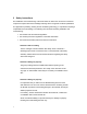
2 Safety instructions The installation and commissioning of the solar station as well as the connection of electrical components requires technical knowledge matching with a recognized vocational qualification as a pipe fitter for plumbing, heating and air conditioning technology, or a profession requiring a comparable level of knowledge.
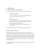
3 Mounting and installing the solar station 1. Remove the front half of the insulation. 2. Hold the solar station against the wall and mark the fastening holes (see figure). 3. Fasten the solar station to the wall with the enclosed anchors and screws. 4. Connect the solar station to the solar thermal system. 5. Check the inlet pressure of the expansion tank and, if necessary, adjust it to the local conditions (inlet pressure = 15 psi + difference in height between the collector and solar station/10). 6.
4 Commissioning 4.1 Flushing and filling the solar thermal system Observe the following safety instructions for commissioning the solar thermal system: Attention: Risk of scalding To prevent the solar fluid boiling in the collectors, the system should not be flushed or filled during periods of strong sunshine. Attention: Risk of freezing Solar thermal systems cannot be completely emptied after flushing. There is a danger of freeze damage if water is used for flushing.
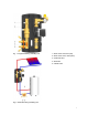
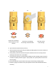
Fig. 1: Integrated flushing and filling unit 1 – Ball / check valve, flow (red) 2 – Ball / check valve, return (blue) 3 – Drain ball valve 4 – Ball valve 5 – Fill ball valve Fig.
4.2 Flushing the storage tank for initial commissioning 1. Connect the pressure hose of a flushing and filling station to the fill ball valve (5). 2. Connect the flushing hose of a flushing and filling station to the fill and drain ball valve at the lowest point of the solar thermal system. 3. Close the ball valve (4). 4. Open the fill ball valve (5) and the fill and drain ball valve at the lowest point of the solar thermal system. 5.
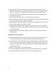
0° Check valve in operation, flow-through only in flow direction 45° 90° Check valve not operating, Ball valve closed, flow-through in both directions no flow-through 6. Open the fill and drain ball valves (3 and 5). 7. Flush the solar thermal system using the flushing and filling station for at least 15 minutes to remove all air from the system. 8. During flushing, bleed the solar thermal system several times at the Air vent (6) until the discharged solar fluid is free of air bubbles. 9.
12. Reconnect the expansion vessel to the other components of the solar thermal system. 13. Set the operating pressure of the solar thermal system by means of the flushing and filling station 5 to 7 psi (0.3 to 0.5 bars) higher than the inlet pressure of the expansion tank. 14. If you have put the flushing and filling station into operation to set the operating pressure, switch off the filling pump. 15. Close the fill and drain ball valves (3 and 5) and open the ball valve (4). 16.
4.4 Emptying the solar thermal system 1. Open the check valves in the ball valves in flow and return (1 and 2, see. fig. 1) by turning the ball valves to a 45° position with an open-ended 14mm wrench. 2. Place a temperature-resistant collection container under the drain ball valve at the lowest point of the solar thermal system. Danger: The discharged fluid can have very high temperatures.
6 Air vent The Air vent (manual bleed valve) is for bleeding the solar fluid in the solar thermal system. The air precipitated from the solar fluid gathers in the upper area of the manual bleed valve (see diagram) and can, if required, be discharged at the bleeding valve. To guarantee faultless bleeding of the collector circuit the flow rate in the flow must be at least 1 f/s (0.3 m/s). Check the system pressure after bleeding and if necessary increase it to the specified operating pressure.
7 Dismantling the solar station To detach the solar station from the wall bracket, remove the clips with a screwdriver and pull the solar station from the wall brackets.
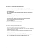
8 Technical data Dimensions: Technical data: Features: Material: 14 Height (with insulation): 15-7/8“ (402 mm) Width (with insulation) 8” (205 mm) Depth (with insulation): 6-7/8” (174 mm) Distance between flow - return: 4” (100 mm) Pipe connections: 1" external thread flat sealing Connection for membrane expansion vessel: ¾" external thread, flat sealing Outlet safety valve: ¾" internal thread Max. permitted pressure 90 psi (6 bars) Max. operating temperature: 250°F (120°C) Max.
9 Replacement parts When ordering replacement parts please state the item no. of the solar station! Pos. Designation Pos.
Caleffi North America, Inc 3883 W. Milwaukee Rd / Milwaukee, WI 53208 Tel: 414.238.2360 / Fax: 414.238.2366 sales@caleffi.com / www.caleffi.