
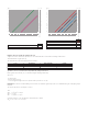
Brochure
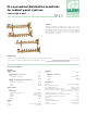
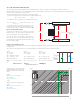
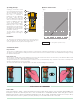

Micrometric balancing valve fully open
Shut-off valve
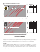
Cv
1.33
3.3
Supply manifold 3 to 7 outlets
Supply manifold 8 to 13 outlets
Return manifold 3 to 7 outlets
Return manifold 8 to 13 outlets
Ball valve
Cv
27.7*
19.6*
38.7*
27.2*
54.9
* Average value
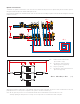
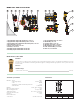
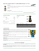
(psi) (kPa)
∆p (psi)
0.01
0.1
0.02
0.03
0.05
0.2
0.3
0.5
0.1
1
0.2
0.3
0.5
2
3
0.04
0.4
1
5
50
100
G (l/h) (
gpm
)
0.1
0.2
0.5
200
1
2
0.01
0.1
0.02
0.03
0.05
0.2
0.3
0.5
0.04
0.4
1
(psi) (kPa)
∆p (psi)
0.01
0.1
0.02
0.03
0.05
0.2
0.3
0.5
0.1
1
0.2
0.3
0.5
2
3
0.04
0.4
1
5
500
1000
G (l/h) (
gpm
)
1
2
5
2000
10
20
0.01
0.1
0.02
0.03
0.05
0.2
0.3
0.5
0.04
0.4
1
Cv = flow in gal/min for a pressure loss of 1 psi
Example of how to calculate the total pressure loss
Suppose we need to calculate the pressure loss of a manifold with three circuits with the following characteristics:
Total manifold flow: 3.0 gpm (400 l/h)
The characteristics of the three piping loops are as follows:
Loop Flow (gpm) Tube length (ft) ∆p (psi)*
1 0.7 150 1.13
2 1.3 300 6.90
3
1.0
300 4.32
*
∆p V
alue for each loop calculated fr
om data published by tubing manufacturers
Each segment of the for
mula
(1.1), is calculated using the following r
elationship:
∆P=G
2
/Cv
2
· G= flow in gpm
·
∆
P = pressure loss in psi
· Cv = flow in gpm through the device in question, with a pressure loss of 1 psi
Impor
tant:
∆
PT
ot
must be calculated taking into account the cir
cuit with the gr
eatest pressure losses distributed along the entire piping loop of
the panel.
The circuit in question in our example is circuit 2.
Thus:
∆
P
BV
= 1.3
2
/1.33
2
= 0.96 psi
∆
P
Loop
= 6.9 psi
∆
P
SV
= 1.3
2
/3.3
2
= 0.16 psi
Using the formula
(1.1) we can add all the calculated terms to obtain:
∆
P
Tot
= 0.96 + 6.90 + 0.16 = 8.02 psi