
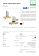
Product Overview
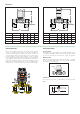

Wiring diagram
Wiring diagram with auxiliary
micro-switch for code 656314
and 656414 actuators:
The auxiliary micro-switch can be
used to turn off the pump when
there is no call for heat and the
valves are closed. If the pump
power consumption exceeds the
contact rating of 5 A, a relay must
be used.
The auxiliary micro-switch shuts off at an average actuator opening
value of 80%.
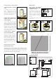
Using the TwisTop™ 656314 actuator
1. Normal operation in automatic
mode.
In automatic mode, the thermo-
electric actuator opens the valve
when is supplied power. The
opening is displayed by the central
disc raising on the top of the knob
and the green circular indicator.
2. Simply twist to manually open
actuator (and activate micro-
switch on 656314).
Turn the knob on the top of the
actuator counterclockwise until the
limit stop trips and the arrow symbols
and hand symbol align. To close the
valve manually and restore automatic
operation, turn the knob clockwise
to “AUTO”. For the 656314 with
auxiliary micro-switch, the micro-
switch contact is closed when in the
manual opening position.
3. When power is applied it
returns to AUTO position.
When the actuator in the manual
position is powered, an internal
mechanism enables automatic
release from the position and a
return to normal operation. A few
seconds after powering up, the
knob will automatically return to the
“AUTO” position and the opening
indicator will stay in the open
position.
Using the 6564 series actuator
Opening/closing indicator
The 656414 thermo-electric actuator, when electrically powered,
opens the valve. The opening is displayed by the central disc raising
on the top of the knob and the green circular indicator. The opening/
closing indicator is especially useful during testing to check for proper
operation without having to activate the system.
Reference documentation for 6564 series: Tech brochure 01198 NA
Open Closed
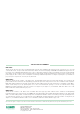
Hydraulic characteristics at 100% open
.03
.06
∆
p
G
(l/s) (
gpm
)
0.1
1
0.2
0.3
0.5
(psi) (kPa)
10
2
3
5
20
1
10
2
3
5
100
20
30
50
0.4
4
4
40
.30
.50
1.4
2.8
5.6
1
0.2
0.5
2
5
10
2
0
5
0
100
2
00
.015
46.00
20.00
10.00
9.00
7.00
5.00
2.00
1.50
1.00
0.70
0.50
0.20
(feet of head)
0.05
3.00
0.30
0.11
0.3
0.5
7.0
12.5
.02
0.3
.10
.20
.70
∆
p
Applications diagram
Shut-off valve
Electric pump
Room thermostat
Check valve
Insulated manifold
RT
CHILLER
RT
Two pipe
system
Cv = 4.0 Kv = 3.5
max 5 A
L
N
˜
OFF
MICRO
OFF
L
N
˜
ON
MICRO
ON
˜
OFF
L
N
˜
OFF
MICRO
OFF
L
N
˜
OFF
MICRO
OFF
L
N
˜
ON
1 = Brown
2 = Blue
3 = Black
4 = Black (656314)
4 = Gray (656414)