
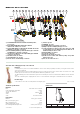
Product Overview
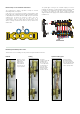

Code 668000S1
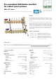
Off-centre fixed setting by-pass kit. Threaded connections 1” x 3/4” female with captive nut. Brass nuts. Gauged copper pipe.
PA check valve obturator, stainless steel spring, EPDM seals, asbestos-free fibre gaskets. Medium water and glycol solutions.
Maximum percentage of glycol 30%. Maximum working pressure 10 bar. Working temperature range 0–100°C. Fixed setting
differential pressure 25 kPa.
SPECIFICATION SUMMARY
BAGNO
CALEFFI
CALEFFI
1
2
3
4
L/MIN
1
2
3
4
L/MIN
1
2
3
4
L/MIN
1
2
3
4
L/MIN
1
2
3
4
L/MIN
HOBBY WC
SOGGIORNO
CAMERA
CALEFFI
BAGNOHOBBY WC
SOGGIORNO
CAMERA
CALEFF
A
B
C
D
CALEFFI
CALEFFI
1
2
3
4
L/MIN
1
2
3
4
L/MIN
WC
SOGGIORNO
WC
SOGGIORNO
A
B
CALEFFI
CALEFFI
1
2
3
4
L/MIN
1
2
3
4
L/MIN
WC
SOGGIORNO
WC
SOGGIORNO
E
21
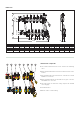
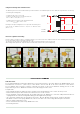
Operating principle
The by-pass valve contains a check obturator integrated with a counter-acting spring.
When the fixed setting differential pressure value is reached, the valve obturator opens gradually.
In this way the flow rate is recirculated and, being proportional to the closure of the thermo-electric valves, keeps the differential pressure in
the manifold circuit at a constant level.
Construction details
The off-centre by-pass kit has a fixed
setting that cannot be changed since it has
no accessible adjustment devices.
The reduced overall dimensions and the
offset connections make this device
particularly easy to install when fitted
as a consequence of the
installation of thermo-electric
valves on the manifold.
Furthermore, its installation
does not require any wider or
deeper zone boxes than those
required for normal manifolds.
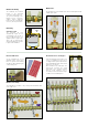
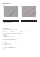
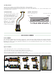
Hydraulic characteristics
By-pass differential pressure: 25 kPa (2500 mm w.g.)
10
20
0,5
1
2
5
0,2
2
0,1
Flow rate
(l/min) (m
3
/h)
∆
p (mm w.g.)
2000
5000
2500
3000
3500
4000
4500
20
50
25
30
35
40
45
∆
p (kPa)
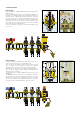
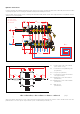
By-pass installation
To fit the differential by-pass on 668...S1 series manifolds, proceed as follows:
1) Close the multi-position valves (A and B) of both end fittings (flow and return).
2) Remove the hose connection (C) from the multi-position valve of the upper manifold.
3) Remove the plastic cap (D) from the end fitting of the lower manifold.
4) Install the differential by-pass kit (E) code 668000S1 and move the multi-position valve levers back into by-pass mode as shown in figure 2