
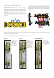
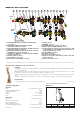
Product Overview
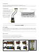

Example of total head loss calculation
Supposing we need to calculate the head loss of a manifold with three circuits with the following characteristics:
Total manifold flow rate: 450 l/h
The flow rate and head loss of the three loops are as follows:
Circuit 1 Circuit 2 Circuit 3
∆P1 = 10 k
Pa ∆P2 = 20 kPa ∆P3 = 7 kPa (1.2)
G1 = 120 l/h G2 = 250 l/h G3 = 80 l/h
Each segment of the formula (1.1) is calculated using the following relationship:
∆P = G
2
/Kv
0,01
2
· G = flow rate in l/h
·
∆
P = head loss in kPa (1 kPa = 100 mm w.g.)
· K
v
0,01
= flow rate in l/h through the device, which corresponds to a head loss of 1 kPa
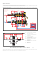
It should be highlighted that the calculation of
∆
PTot. must be made taking account of the circuit in which there are the greatest head losses
distributed along the entire panel pipe loop.
In the case we are examining, the relevant circuit is No. 2.
It follows that:
∆
P
BV2
= 250
2
/185
2
= 1,82 kPa
∆
P
Loop2
= 20 kPa
∆
P
SV2
= 250
2
/250
2
= 1 kPa
∆
P
Manif. F
= 450
2
/2100
2
= 0,04 kPa
}
Values obtained by disregarding changes due to drawing off flow rate to the individual branched circuits
∆
P
Manif. R
= 450
2
/2100
2
= 0,04 kPa
∆
P
VB
= 450
2
/4750
2
= 0,01 kPa
Using formula (1.1), adding up all the calculated terms, we obtain:
∆
P
Tot.
= 1,82 + 20 + 1 + 0,04 + 0,04 + 0,01x2 = 22,82 kPa
Note:
We can ignore the three terms for the head losses associated with the ball valves and manifolds because of their low values.
In general, the total head loss is fairly close to the branched panel circuit head loss.
20
1000
100
100
G (l/h)
∆p (mm w.g.)
200
50
500
25
30
35
40
45
50
60
70
80
90
120
140
160
180
200
900
800
700
600
60
70
80
90
120
140
160
180
250
300
350
400
450
10
1
2
0,5
5
9
8
7
6
0,6
0,7
0,8
0,9
1,2
1,4
1,6
1,8
2,5
3
3,5
4
4,5
∆p (kPa)
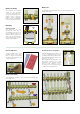
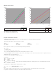
Flow rate balancing valve fully open (BV)
Panel circuit shut-off valve (SV)
Kv
1,85
2,50
Kv
0,01
185
250
250
300
350
400
450
500
10
20
12
14
16
18
25
30
35
40
45
0,1
0,2
0,
12
0,
14
0,
16
0,
18
0,
25
0,
3
0,
35
0,
4
0,
45
Flow or return manifold, 3 – 7 outlets
Flow or return manifold, 8 – 14 outlets
Ball valve (VB)
Kv
21,0
*
14,0*
47,5
Kv
0,01
2100*
1400*
4750
1000
100
G (l/h)
∆p (mm w.g.)
200
50
500
900
800
700
600
60
70
80
90
120
140
160
180
250
300
350
400
450
∆p (kPa)
500
10
20
12
14
16
18
25
30
35
40
45
10
1
2
0,5
5
9
8
7
6
0,6
0,7
0,8
0,9
1,2
1,4
1,6
1,8
2,5
3
3,5
4
4,5
0,1
0,2
0,
12
0,
14
0,
16
0,
18
0,
25
0,
3
0,
35
0,
4
0,
45
1000
600
700
800
900
1200
1400
1600
1800
2000
250
0
300
0
350
0
4
000
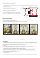
* Average value
- Kv = portata in m
3
/h per una perdita di carico di 1 bar
- Kv
0,01
= portata in l/h per una perdita di carico di kPa
- Kv = flow rate in m
3
/h for a head loss of 1 bar
- Kv
0,01
= flow rate in l/h for a head loss of 1 kPa
Hydraulic characteristics