
Product Overview
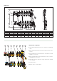
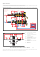

Using the balancing valves with flow meter
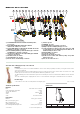
The balancing valves in the flow manifold make it possible to balance each individual panel circuit to obtain the design flow rates in each loop.
Considering the following data:
- medium flow rate across each circuit
- head loss generated in each circuit by this flow rate:
∆
P
Circuit
=
∆
P
Loop
+
∆
P
SV
(
∆
P
Shut-off valve
)
- available head on the panel circuit or predefined head:
H
Predefined
≥
∆
P
Circuit +
=
∆
P
BV
+
∆
P
Loop
+
∆
P
SV
disadvantaged
Referring to the adjacent diagram,
for the loop flow rate the balacing valve
must provide an additional head loss equal to the difference
∆
P
BV
(
∆
P
Balancing valve
).
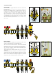
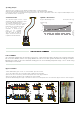
Flow rate regulation and reading
Lift the locking cover with the aid of a screwdriver and turn it over onto the flow meter. Adjust the flow rate of the individual panels by turning
the flow meter body acting on the built-in regulating valve.
The flow rate must be read on the graduated scale, expressed in l/min, printed on the flow meter itself.
After making all the adjustments, reposition and lock all the knobs in their seats to prevent tampering.
HPredefined ≥ ∆PCircuit
+ disadvantaged
∆PBV
∆PCircuit
∆P
Tot.
SV
BV
SYSTEM
FLOW
SYSTEM
RETURN
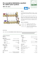
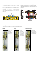
668…S1 series
Pre-assembled distribution manifold for radiant panel systems with 3 (from 3 to 14) outlets. Brass body. EPDM hydraulic seals.
Threaded main connections 1” (and 1 1/4”) F, centre distance 195 mm. 3/4” M - Ø 18 outlet connections, centre distance
50 mm. Medium water and glycol solutions; maximum percentage of glycol 30%. Maximum working pressure 10 bar.
Temperature range 0–80°C. Maximum automatic air vent discharge pressure 2,5 bar.
Complete with:
- Flow manifold with flow rate balancing valves and flow meters with graduated scale 1–5 l/min. Accuracy ±15%.
- Return manifold complete with shut-off valves fitted for thermo-electric actuator.
- Pair of end fittings complete with automatic air vent with hygroscopic cap, fill/drain hose connection, multi-position ball valves for
coupling with the off-centre fixed setting differential by-pass kit supplied in the package.
- Off-centre fixed setting by-pass kit. Threaded connections 1” M x 3/4” M. Brass body and nuts. Gauged copper pipe.
PA obturator, stainless steel spring, EPDM seals, asbestos-free fibre seals. Fixed setting differential pressure 25 kPa.
- Adhesive labels indicating the rooms.
- Pair of shut-off ball valves, brass body. EPDM union seals.
- Pair of fixing brackets.
SPECIFICATION SUMMARY